Friday, December 12, 2025

Defence Minister Shri Rajnath Singh today virtually inaugurated 125 major infrastructure projects across the country.

ЁЯЗоЁЯЗ│ A proud moment for the nation!

Defence Minister Shri Rajnath Singh today virtually inaugurated 125 major infrastructure projects across the country.

Among these, seven key projects from Uttarakhand have also been launched, including the opening of five strategic bridges built in the border region of Niti Pass in Chamoli district:

Suraithota Bridge

Pangthi Bridge

Gurkutti Bridge

Gamsali Bridge

Niti Bridge

ЁЯПФ️ Located close to the India–China border, these high-altitude areas will now have safer and smoother access.

These bridges will:

Strengthen the movement of the Army and paramilitary forces

Provide major relief to residents of border villages
Boost connectivity and development in the region
A wave of happiness is visible among the local people—these bridges are not just physical structures, but pathways to progress, security, and new opportunities.

DM Gaurav Kumar Chairs Review on Land Transfer, Arbitration & Highway Widening

District Review on NH-07: Land Transfers & Road-Widening Progress


Under the chairmanship of District Magistrate Gaurav Kumar, a review meeting was held on Thursday with NHIDCL, BRO, and the Rail Vikas Nigam regarding pending cases related to land acquisition, transfer of forest and civil land, and road-widening issues. He directed that all pending land-transfer matters be resolved promptly so that the remaining project works can be completed without delay. He also instructed that swift action be taken in arbitration-related cases as per the decisions already issued. Coordination with the respective tehsils was emphasized to ensure timely disposal of mutation cases.

Regarding the remaining widening work on National Highway-07 between Nandprayag and Chamoli, particularly near Chada (Chamoli), the District Magistrate instructed NHIDCL to coordinate with the SDM to expedite the widening activities. He stressed that traffic must not be disrupted during road-cutting operations. Additionally, he directed the agency to construct protective walls at the dumping zones and level the area to ensure safety.

#Chamoli #NH7 #BadrinathHighway #LandAcquisition #RoadSafety #NHIDCL #BRO


Thursday, April 17, 2025

Break Through Done at Silkyara Tunnel :

Break Through Done at Silkyara Tunnel : 

The last blast of Silkyara Tunnel was done in the presence of MD NHIDCL. Hon’ble CM Uttrakhand and Hon’ble MoS, RTH graced the occasion. Pooja was also performed in the new Temple constructed by NHIDCL near Silkyara portal. 
Hon'ble CM and Hon'ble MoS appreciated the work of NHIDCL in such dificult terrains and extended specials thanks to MD sir at the stage ceremony .

Tuesday, March 4, 2025

What is Bally Benching Process?

The Bally Benching Process is a slope stabilization technique used for slope protection, especially in hilly terrains and construction sites where landslides or erosion could occur. This method involves creating stepped or benched terraces along the slope to reduce erosion, improve stability, and provide a base for further protective measures like vegetation or retaining structures.
Process of Bally Benching for Slope Protection
1. Site Assessment & Survey Determine slope angle, soil type, and risk factors.
Identify natural drainage patterns and weak zones.
2. Marking & Excavation

The slope is divided into horizontal steps (benches).
Each bench is cut into the slope at a controlled angle, reducing the steepness.

3. Compaction & Drainage Installation

Compaction of benches to prevent soil erosion.
Installation of drainage channels to redirect water flow.

4. Slope Protection Measures
Using geotextiles, stone pitching, or vegetation to stabilize soil.
Retaining walls or gabion walls can be added if necessary.
5. Final Inspection & Maintenance
Regular monitoring for erosion or structural failures.
Repairs and additional planting if needed.
Example of Bally Benching in Use
Highway Cut Slopes: Used on hill roads to stabilize slopes and prevent landslides.
Mining Areas: Controls soil erosion and helps in reclamation.
Agricultural Terraces: Prevents soil loss in hilly farming lands.
Images of Bally Benching Process

Sunday, January 19, 2025

125 рдХिрд▓ोрдоीрдЯрд░ рд▓ंрдмी рдЛрд╖िрдХेрд╢-рдХрд░्рдгрдк्рд░рдпाрдЧ рд░ेрд▓ рдкрд░िрдпोрдЬрдиा

рдоुрдЦ्рдпрдоंрдд्рд░ी рд╢्рд░ी рдкुрд╖्рдХрд░ рд╕िंрд╣ рдзाрдоी рдиे рд╢рдиिрд╡ाрд░ рдХो рдЬрдирдкрдж рдЪрдоोрд▓ी рдХे рдХрд░्рдгрдк्рд░рдпाрдЧ, рд╕ेрд╡ाрдИ рдоें рд╕ंрдЪाрд▓िрдд рдЛрд╖िрдХेрд╢-рдХрд░्рдгрдк्рд░рдпाрдЧ рд░ेрд▓ рдкрд░िрдпोрдЬрдиा рдХे рдХाрд░्рдпो рдХा рд╕्рдерд▓ीрдп рдиिрд░ीрдХ्рд╖рдг рдХिрдпा।

 рдЙрди्рд╣ोंрдиे рд░ेрд▓ рд╡िрдХाрд╕ рдиिрдЧрдо рд▓िрдоिрдЯेрдб рдХे рдЕрдзिрдХाрд░िрдпों рд╕े рд░ेрд▓рд╡े рд╕्рдЯेрд╢рди рдкрд░ рдХिрдП рдЬा рд░рд╣े рдХाрд░्рдпों, рдЕрд╡рд╕्рдеाрдкрдиा рд╕ुрд╡िрдзाрдУं рдФрд░ рдкрд░िрдпोрдЬрдиा рдХी рдк्рд░рдЧрддि рдХे рдмाрд░े рдоें рд╡िрд╕्рддाрд░ рд╕े рдЬाрдирдХाрд░ी рд▓ी। рдЗрд╕ рджौрд░ाрди рдоुрдЦ्рдпрдоंрдд्рд░ी рдиे рдкрд░िрдпोрдЬрдиा рдоें рдЕрдкрдиी рдорд╣рдд्рд╡рдкूрд░्рдг рднूрдоिрдХा рдиिрднा рд░рд╣े рд╢्рд░рдоिрдХों рд╕े рдоुрд▓ाрдХाрдд рдХрд░ рдЙрдирдХा рднी рдХुрд╢рд▓рдХ्рд╖ेрдо рднी рдЬाрдиा। рдоुрдЦ्рдпрдоंрдд्рд░ी рдиे рдХрд╣ा рдХि рдк्рд░рдзाрдирдоंрдд्рд░ी рдЬी рдХे рдиेрддृрдд्рд╡ рдПрд╡ं рдоाрд░्рдЧрджрд░्рд╢рди рдоें рдЕрдм рдкрд╣ाрдб़ो рддрдХ рд░ेрд▓ рдкрд╣ुंрдЪрдиे рдХा рд╕рдкрдиा рдкूрд░ा рд╣ो рд░рд╣ा рд╣ै। рдоुрдЦ्рдпрдоंрдд्рд░ी рдиे рдХрд╣ा рдХि рдЛрд╖िрдХेрд╢-рдХрд░्рдгрдк्рд░рдпाрдЧ рд░ेрд▓ рд▓ाрдЗрди рдХा рдиिрд░्рдоाрдг рдХाрд░्рдп рдкूрд░ा рд╣ोрдиे рдХे рдмाрдж рдк्рд░рджेрд╢рд╡ाрд╕िрдпों рдХो рди рдХेрд╡рд▓ рдпрд╣ рдпाрддाрдпाрдд рд╕ुрд╡िрдзा рдоिрд▓ेрдЧी, рдмрд▓्рдХि рдмрдж्рд░ीрдиाрде рдФрд░ рдХेрджाрд░рдиाрде рдЖрдиे рд╡ाрд▓े рддीрд░्рдердпाрдд्рд░िрдпों рдФрд░ рдкрд░्рдпрдЯрдХों рдХो рднी рдЗрд╕рдХा рднрд░рдкूрд░ рд▓ाрдн рдоिрд▓ेрдЧा। рд░ेрд▓ рдкрд░िрдпोрдЬрдиा рдХे рдЕрдзिрдХाрд░िрдпों рдиे рдмрддाрдпा рдХि 125 рдХिрд▓ोрдоीрдЯрд░ рд▓ंрдмी рдЛрд╖िрдХेрд╢-рдХрд░्рдгрдк्рд░рдпाрдЧ рд░ेрд▓ рдкрд░िрдпोрдЬрдиा рдкрд░ 16 рдЯрдирд▓ рдФрд░ 12 рд╕्рдЯेрд╢рди рдмрди рд░рд╣े рд╣ै। рдЖрдЧाрдоी 2026 рджिрд╕ंрдмрд░ рддрдХ рдЗрд╕ рдкрд░िрдпोрдЬрдиा рдХा рдЕрдзिрдХांрд╢ рдХाрд░्рдп рдкूрд░्рдг рдХрд░рдиे рдХा рд▓рдХ्рд╖्рдп рд░рдЦा рдЧрдпा рд╣ै। рдЧौрдЪрд░ рдХे рднрдЯ्рдЯрдирдЧрд░ рд╕े рд╕ेрд╡ाрдИ рддрдХ 6.3 рдХिрдоी рд╕्рдХेрдк рдЯрдирд▓ рд╡िрдЧрдд 25 рджिрд╕ंрдмрд░ рдХो рдм्рд░ेрдХ рде्рд░ू рд╣ो рдЪुрдХी рд╣ै, рдЬрдмрдХि 6.2 рдХिрд▓ोрдоीрдЯрд░ рдоेрди рдЯрдирд▓ рдЖрдЧाрдоी рдоाрд░्рдЪ рдоें рдм्рд░ेрдХ рде्рд░ू рд╣ो рдЬाрдПрдЧी।

125-kilometer-long Rishikesh-Karnaprayag rail project

Chief Minister Pushkar Singh Dhami conducted an on-site inspection of the works under the Rishikesh-Karnaprayag Rail Project at Sewai, Karnaprayag, in Chamoli district on Saturday. He reviewed the progress of the railway station construction, infrastructure facilities, and the overall advancement of the project with officials from Rail Vikas Nigam Limited. During the visit, the Chief Minister also interacted with the workers contributing significantly to the project and inquired about their well-being.


The Chief Minister stated that under the leadership and guidance of Prime Minister Narendra Modi, the dream of extending rail connectivity to the hills is becoming a reality. He emphasized that the completion of the Rishikesh-Karnaprayag rail line would not only enhance transportation for the residents of the state but also provide significant benefits to pilgrims and tourists visiting Badrinath and Kedarnath.

Officials of the rail project informed that the 125-kilometer-long Rishikesh-Karnaprayag rail project includes the construction of 16 tunnels and 12 stations. The majority of the project is expected to be completed by December 2026. They also reported that the 6.3-kilometer escape tunnel from Bhattnagar, Gauchar, to Sewai achieved a breakthrough on December 25, while the 6.2-kilometer main tunnel is expected to achieve a breakthrough by March.


Kedarnath Forest Division for installing these advanced bio-digester toilets

To provide better facilities for pilgrims on the Rudranath Yatra route, DRDO's green, high-tech, prefabricated bio-toilets will be installed. District Magistrate Sandeep Tiwari has allocated ₹30 lakh to the Kedarnath Forest Division for installing these advanced bio-digester toilets. Before the upcoming yatra season, 10 bio-digester toilets will be established along the Rudranath Yatra route. Of these, 4 will be installed at Rudranath, 4 at Lwiti, and 2 at Mauli Khark.

The District Magistrate stated that efforts are being made to provide all necessary facilities for pilgrims on the yatra route as per the directives of Chief Minister Pushkar Singh Dhami. The Defence Research and Development Organisation (DRDO) has developed an environmentally friendly, maintenance-free, and cost-effective bio-digester technology for human waste disposal in high-altitude areas. These bio-toilets are equipped with a bio-digester container underneath, which contains anaerobic bacteria. These bacteria convert sewage waste into water and gas. This clean technology eliminates the problem of sewage waste disposal, making it highly efficient and eco-friendly.

Penalty imposed for RG Buildwell Engineers Limited

A penalty of ₹116 lakh has been imposed on the contractor for failing to complete the Pokhri-Karnaprayag motor road project within the stipulated time. Executive Engineer Rajkumar of the Public Works Department (PWD), Pokhri, stated that a contract was signed with RG Buildwell Engineers Limited for the improvement and BM/SDBC tarring of the Pokhri-Karnaprayag motor road. According to the contract, the work was to commence on August 30, 2022, and be completed by February 29, 2024. However, the progress of the improvement work has been significantly delayed.

Despite repeated written reminders to the contractor, the work remains incomplete. Consequently, a penalty of ₹116 lakh has been imposed on the contractor as per the terms of the contract. Additionally, the Superintending Engineer, 7th Circle, PWD Gopeshwar, has issued a show-cause notice to the contractor regarding this matter.


рдЪрдоोрд▓ी рдЬрдирдкрдж рдоुрдЦ्рдпाрд▓рдп рдЧोрдкेрд╢्рд╡рд░ рдоें рдХेंрдж्рд░ीрдп рд╡िрдж्рдпाрд▓рдп рдХा рдирдпा рднрд╡рди

рдЪрдоोрд▓ी рдЬрдирдкрдж рдоुрдЦ्рдпाрд▓рдп рдЧोрдкेрд╢्рд╡рд░ рдоें рдХेंрдж्рд░ीрдп рд╡िрдж्рдпाрд▓рдп рдХा рдирдпा рднрд╡рди рдмрдирдХрд░ рддैрдпाрд░ рд╣ो рдЧрдпा рд╣ै। рдЬिрд▓ाрдзिрдХाрд░ी рд╕ंрджीрдк рддिрд╡ाрд░ी рдиे рд╢ुрдХ्рд░рд╡ाрд░ рдХो рдХेंрдж्рд░ीрдп рд╡िрдж्рдпाрд▓рдп рдХे рдирд╡рдиिрд░्рдоिрдд рднрд╡рди рдХा рд╕्рдерд▓ीрдп рдиिрд░ीрдХ्рд╖рдг рдХिрдпा। рдЗрд╕ рджौрд░ाрди рдЬिрд▓ाрдзिрдХाрд░ी рдиे рд╡िрдж्рдпाрд▓рдп рднрд╡рди рдоें рдиिрд░्рдоिрдд рдХрдХ्рд╖ा рдХрдХ्рд╖, рдк्рд░рдпोрдЧрд╢ाрд▓ा, рдХैंрдЯीрди, рд╢ौрдЪाрд▓рдп, рдмрдЪ्рдЪों рдХी рд╕ुрд░рдХ्рд╖ा рдХे рд░ैрд▓िंрдЧ, рдЦेрд▓ рдоैрджाрди, рдб्рд░ेрдиेрдЬ рд╕िрд╕्рдЯрдо рдПрд╡ं рдЕрди्рдп рд╡्рдпрд╡рд╕्рдеाрдУं рдХा рдЬाрдпрдЬा рд▓िрдпा। рдЬिрд▓ाрдзिрдХाрд░ी рдиे рдиिрд░्рджेрд╢िрдд рдХिрдпा рдХि рд╡िрдж्рдпाрд▓рдп рднрд╡рди рдоें рдмिрдЬрд▓ी, рдкाрдиी рдФрд░ рдлाрдпрд░ рд╕ेрдл्рдЯी рдХी рддрдХрдиीрдХी рдиिрд░ीрдХ्рд╖рдг рдХे рд▓िрдП рд╕рдоिрддि рдЧрдаिрдд рдХрд░рддे рд╣ुрдП рд░िрдкोрд░्рдЯ рдЙрдкрд▓рдм्рдз рдХрд░ें рдФрд░ рд╕рдоिрддि рдХी рд░िрдкोрд░्рдЯ рдХे рдЕрдиुрд╕ाрд░ рдЗрд╕рдоें рдЬो рднी рдХрдоिрдпां рдкрд░िрд▓рдХ्рд╖िрдд рд╣ोрддी рд╣ै, рддो рдЙрд╕рдХो рджूрд░ рдХрд░рддे рд╣ुрдП рдпрдеाрд╢ीрдШ्рд░ рд╡िрдж्рдпाрд▓рдп рднрд╡рди рдХो рд╣рд╕्рддांрддрд░िрдд рдХिрдпा рдЬाрдП। рдЬिрд▓ाрдзिрдХाрд░ी рдиे рдЬрд▓्рдж рд╕े рдЬрд▓्рдж рдирдП рднрд╡рди рдоें рд╡िрдж्рдпाрд▓рдп рдХा рд╕ंрдЪाрд▓рди рд╢ुрд░ू рдХрд░ाрдиे рдХे рдиिрд░्рджेрд╢ рднी рджिрдП। рдЗрд╕ рджौрд░ाрди рдЬिрд▓ाрдзिрдХाрд░ी рдиे рдХेंрдж्рд░ीрдп рд╡िрдж्рдпाрд▓рдп рдкंрдЬीрдХृрдд рдмрдЪ्рдЪों рдХी рд╕ंрдЦ्рдпा рдФрд░ рд╕्рдЯाрдл рдХे рдмाрд░े рдоें рднी рдЬाрдирдХाрд░ी рд▓ी। рдХाрд░्рдпрджाрдпी рд╕ंрд╕्рдеा рд╕ीрдПрдбंрдбीрдПрд╕ рдпूрдкी рдЬрд▓ рдиिрдЧрдо рдХे рдЗंрдЬीрдиिрдпрд░्рд╕ рдордиोрдЬ рдХुрдоाрд░ рдФрд░ рд╕ाрдЗрдЯ рдЗंрдЬीрдиिрдпрд░ рд╕ंрддोрд╖ рд╕िंрд╣ рдиे рдмрддाрдпा рдХि рддीрди рдПрдХреЬ рдХ्рд╖ेрдд्рд░рдлрд▓ рдоें 30.29 рдХрд░ोреЬ рдХी рд▓ाрдЧрдд рд╕े рдХेंрдж्рд░ीрдп рд╡िрдж्рдпाрд▓рдп рднрд╡рди, 08 рд╕्рдЯाрдл рдХ्рд╡ाрдЯрд░, 01 рдк्рд░рдзाрдиाрдЪाрд░्рдп рдЖрд╡ाрд╕, рдЦेрд▓ рдоैрджाрди, рдЪाрд░ рджीрд╡ाрд░ी рдПрд╡ं рдЕрди्рдп рд╕рднी рд╕्рд╡ीрдХृрдд рдиिрд░्рдоाрдг рдХाрд░्рдп рдкूрд░्рдг рдХрд░ рджिрдП рдЧрдП рд╣ै। 

The newly constructed building of Kendriya Vidyalaya in Gopeshwar

The newly constructed building of Kendriya Vidyalaya in Gopeshwar, the district headquarters of Chamoli, has been completed. District Magistrate Sandeep Tiwari conducted an on-site inspection of the newly constructed school building on Friday. During the visit, the District Magistrate reviewed the classrooms, laboratories, canteen, toilets, safety railings for children, playground, drainage system, and other facilities in the school building. He instructed that a technical inspection committee be constituted to examine the provisions for electricity, water, and fire safety, and a report be submitted. Based on the committee's findings, any deficiencies observed should be rectified promptly, and the school building should be handed over without delay.


The District Magistrate also directed that operations at the new building be commenced at the earliest. Additionally, he inquired about the number of registered students and the staff of Kendriya Vidyalaya. Engineers Manoj Kumar and site engineer Santosh Singh from the implementing agency, C&DS UP Jal Nigam, informed that all approved construction work, including the school building, eight staff quarters, one principal's residence, a playground, boundary walls, and other facilities, has been completed on three acres of land at a cost of ₹30.29 crores.


Monday, September 2, 2024

Types of drawings in any construction project:

Types of drawings in any construction project:

1. IFC Drawing:

Detailed drawings considered final, issued, and approved by the design team for construction, reflect precise dimensions, layout, and specifications. It can used by GCs to execute construction according to the contract, and also serve as a legal record of the design.

2. Construction Drawings:

These drawings provide an overview of the entire project, its floor plans, elevations, sections, and site plan. These documents are used in bidding and early construction stages.

3. Shop Drawing:

Detailed drawings produced by contractors or sub-contractors, illustrating specific components, systems, or installations according to design.

4. As-Built Drawings:

Drawings created during or after construction that show/reflect the actual conditions of the project, including any changes or modifications made during construction.

Summary:

i. IFC drawings represent the entire project design.

ii. Shop drawings focus on specific components.

iii. Construction drawings provide an overview.

iv. As-built drawings capture the final built state.

Thursday, June 8, 2023

рджिрд▓्рд▓ी рд╕рд╣ाрд░рдирдкुрд░ рджेрд╣рд░ाрджूрди рдПрдХ्рд╕рдк्рд░ेрд╕рд╡े

9 рдиिрд░्рдоाрдг рдлрд░्рдоों рдиे 18 рдордИ 2022 рдХो  210 рдХिрд▓ोрдоीрдЯрд░ рджिрд▓्рд▓ी-рд╕рд╣ाрд░рдирдкुрд░-рджेрд╣рд░ाрджूрди рдПрдХ्рд╕рдк्рд░ेрд╕рд╡े рдХे рдЪрд░рдг 3 рдХे 18.47 рдХिрд▓ोрдоीрдЯрд░ рдкैрдХेрдЬ 2 рдХे рдиिрд░्рдоाрдг рдХे рд▓िрдП рдмोрд▓िрдпां рдЬрдоा рдХीं।
 рдпрд╣ 6 рд▓ेрди рдЬ्рдпाрджाрддрд░ рдЧ्рд░ीрдирдлीрд▓्рдб рдПрдХ्рд╕рдк्рд░ेрд╕рд╡े 4 рдЪрд░рдгों рдоें рд╡िрдХрд╕िрдд рдХिрдпा рдЬा рд░рд╣ा рд╣ै। рдЗрд╕рдХे 40 рдХिрд▓ोрдоीрдЯрд░ рдХे рдЪрд░рдг 3 рдоें NH-307 рдХो рдЙрдд्рддрд░ рдк्рд░рджेрд╢ рдХे рд╕рд╣ाрд░рдирдкुрд░ рдмाрдИрдкाрд╕ рдФрд░ рдЙрдд्рддрд░ाрдЦंрдб рдХे рдЧрдгेрд╢рдкुрд░ рдХे рдмीрдЪ 6 рд▓ेрди рдХे рдПрдХ्рд╕ेрд╕-рдиिрдпंрдд्рд░िрдд рд░ाрдЬрдоाрд░्рдЧ рдоें рдЕрдкрдЧ्рд░ेрдб рдХिрдпा рдЬाрдПрдЧा।

 рдЗрд╕ рдкैрдХेрдЬ рдоें 2 рдиिрд░ंрддрд░ рдЦंрдб рд╢ाрдоिрд▓ рд╣ैं।
 рдФрд░ рдЗрд╕рдХी рд╡िрд╕्рддृрдд рдкрд░िрдпोрдЬрдиा рд░िрдкोрд░्рдЯ (рдбीрдкीрдЖрд░) рдЯ्рд░ांрд╕िрд╕ рдХंрд╕рд▓्рдЯिंрдЧ рдк्рд░ाрдЗрд╡ेрдЯ рд▓िрдоिрдЯेрдб рдж्рд╡ाрд░ा рддैрдпाрд░ рдХी рдЧрдИ рдеी। 
 рднाрд░рддीрдп рд░ाрд╖्рдЯ्рд░ीрдп рд░ाрдЬрдоाрд░्рдЧ рдк्рд░ाрдзिрдХрд░рдг (NHAI) рдиे рдЬрдирд╡рд░ी 2022 рдоें рдЕрдкрдиे рдиिрд░्рдоाрдг рдЕрдиुрдмंрдз рдХे рд▓िрдП рд░ुрдкрдпे рдХे рд╕ाрде рдиिрд╡िрджाрдПं рдЖрдоंрдд्рд░िрдд рдХीं। 495.85 рдХрд░ोрдб़ рдЕрдиुрдоाрди рдФрд░ 10 рд╕ाрд▓ рдХी рд░рдЦрд░рдЦाрд╡ рдЕрд╡рдзि। 

рдПрдирдПрдЪрдПрдЖрдИ рдХा рд╕ंрдХ्рд╖िрдк्рдд рджाрдпрд░ा: рдмीрдПрдордкी рдЪрд░рдг-1 (рдкैрдХेрдЬ-2) рдХे рддрд╣рдд рдИрдкीрд╕ी рдкрд░ рдЙрдд्рддрд░ рдк्рд░рджेрд╢ рдФрд░ рдЙрдд्рддрд░ाрдЦंрдб рдоें рд╕рд╣ाрд░рдирдкुрд░ рдмाрдИрдкाрд╕ рд╕े рджिрд▓्рд▓ी рджेрд╣рд░ाрджूрди рдИрд╕ी рдХे рдЧрдгेрд╢рдкुрд░ рдЦंрдб рддрдХ рдХे рд╣िрд╕्рд╕ों рдоें рдкूрд░्рдг рдЕрднिрдЧрдо рдиिрдпंрдд्рд░рдг рдк्рд░ाрд╡рдзाрдиों рдХे рд╕ाрде рдЫрд╣ рд▓ेрди (рдкैрдХेрдЬ -2)। 

Flexible Pavement, Construction of Road or Highway

Construction of Road/ Highway
There are two types of Road Construction.
 1.) Flexible Roads/Pavement
 2.) Rigid Roads/Pavement
 In Flexible Road Construction
 Total length of thickness=570mm
 a) GSB Layers=300 mm
 b) Wet mix macadam (WMM) Layer=120 to 150 mm
 c)  Dense Bituminous Macadam (DBM) = 80 mm
 d) Bituminous Course (BC)/Wearing Course = 40 mm
 Total =300+150+80+40
           =570 mm

Flexible Pavement 
A pavement which consists of a mixture of asphaltic or bituminous material and aggregate placed on a good quality and compacted granular material is called flexible pavement. Example of flexible pavement water bound macadam roads . 
The essential points of flexible pavement 
(i) The flexible pavements have self revive properties.whatever deformation arise in flexible pavement due to massive wheel loads, it is regeneration to some extent after some time. 
(ii) The temperature variations due to changes in atmospheric conditions do not produce stresses in flexible pavement. 
(iii) The structural capacity of the flexible pavement is influenced by strength of the sub-grade. 
(iv) The cost of construction of flexible pavements is less than compared to rigid pavement. 

California bearing Ratio Method

Construction of Road/ Highway
There are two types of Road Construction.
 1.) Flexible Roads/Pavement
 2.) Rigid Roads/Pavement
 In Flexible Road Construction
 Total length of thickness=570mm
 a) GSB Layers=300 mm
 b) Wet mix macadam (WMM) Layer=120 to 150 mm
 c) Dense Bituminous Macadam (DBM) = 80 mm
 d) Bituminous Course (BC)/Wearing Course = 40 mm
 Total =300+150+80+40
           =570 mm
California bearing Ratio Method 
The California bearing ratio of a soil which ranges from 0 to 100 % , gives a value about the quality of a material contrast to that of a magnificent base material for which the C.B.R. is assumed to be 100 percent. 
There are many versions of C.B.R. method of flexible pavement design. 
 
This is a penetration test developed by the California Division of Highways to evaluate the stability of soil sub-grade and other flexible pavement. 
It contains a standard piston have a diameter of 50 mm which is used to penetrate the soil at the standard value of 1.25 mm/min. 
Test Procedure
(a) Laboratory CBR apparatus contain a mold of 150 mm diameter with a base plate and a collar, a loading framework and dial gauges to evaluate the penetration. 
(b)The specimen of soil is soaked in water for 4 days, and swelling and water absorption values is noted. 
(c) Load is applied on the samples by a standard plunger with diameter of 50 mm at the rate of 1.25 mm/minutes.
(d) A graph is plotted between the load or pressure and penetration. 
(e) Load values are noted corresponding to the 2.5 mm and 5.0 mm penetration.
 (f) Calculate the CBR value corresponding to 2.5 mm and 5.0 mm. 
CBR% = (Load carried by specimen at 2.5 or 5.0 mm penetration/ Load carried b standard aggregates at a corresponding penetration level ) x 100
 Standard Load Values 
Penetration (mm)  Load (Kg) Pressure (Kg/Cm^2) 
2.5   1370 70 
5.0 2055 105
 (g) Average CBR value of three test specimens is reported as the CBR value of the sample. Table.1 Typical CBR values of soils and their rating 
Soil Range of CBR values   Rating
Clay.    2-5     very poor Subgradade
Silt           5-8 Poor Subgrade
 Sand    8-20 Fair to good Subgrade
GRAVEL 20-30  Excellent Sub grade  

What do you understand by Water cement ratio? How the quantity of water affects the strength of a Concrete mix?

 WATER CEMENT RATIO
The ratio of the volume of water to volume of cement used in a concrete mix is called water cement ratio. 
By Water. Cement ratio Law
According to water cement ratio Law, "For any given condition of test, the strength of well compacted Concrete with good workability is dependent only on the water cement ratio."
The workability of Concrete is dependent to other factors like grading of Concrete, proportion of aggregates, proportion of cement, and the efficiency of mixture etc. Also depends upon the quantity of water used in the mixture.
According to Abram law the strength of mixture increases not merely by increasing the quantity of cement in the mix but it is an account it of reducing the water cement ratio the strength of concrete in accordance with the the law is given by modified formula.
P28= 984/4^x
Where P28 = Cylinder Crushing Strength of Concrete in Kg/cm^2
X= Water Cement ratio by volume
The observation results, it is observed that for a given proportion of ingredients in a design concrete mix, there is almost a certain around of water (optimum) which gives maximum strength.
 A small changes in the quantity of water reason much higher variation in the strength of concrete.
 In case the water used is less, the resultant concrete will be comparatively dry, difficult to place in position and may pose problems in compaction.
 Moreover, with less water complete setting of cement cannot be ensured and hence the strength of concrete get reduced appreciably.
 On the other hand, in case the water is more it would Tesult in formation cr excessive voids and honey-combing in the set concrete, thereby reducing its density, strength and durability.
 so that, water cement ratio determine as a yard stick for achieving concrete of define strength.
 The lower the water cement ratio, the larger is the strength of the Design mix of Concrete. 
A rich mix of concrete gives higher strength than a lean mix, not because of more cenent but it is on account of the fact that concrete can be used with a lower water cement ratio.

SHOTCRETING OF Slope Protection Work

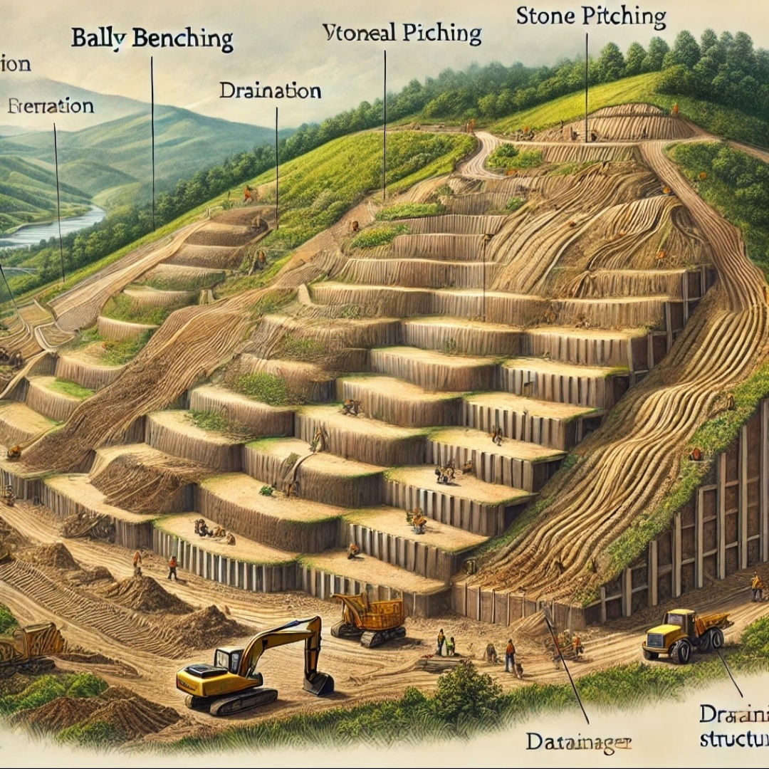
METHODOLOGY FOR SLOPE PROTECTION WORKS 

A. METHODOLGY FOR SHOTCRETING
1. A better base or foundation is necessary for conventional and successful application of shotcrete. 
Where the shotcrete is to be placed against earth surfaces as linings, such surfaces shall first be thoroughly compacted and trimmed to line and grade. Shotcrete shall not be placed on any surface which is frozen, spongy, or where there is frequent water. 
The surface shall be kept damp for several hours before applying shotcrete. 
2. Adequate and safe scaffolding shall be provided so that the operator can hold the nozzle at the optimum angle and distance from the surface for all parts of the work. 
The scaffolding shall be also given easy approach to the shotcrete surface for to assist in flattening and finishing, if such is specified. Scaffolding shall be constructed to permit undisturbed applications of the shotcrete wherever possible.
3. Sufficient clearance shall be provided around the wire mesh to permit complete encasement with sound concrete. 
The clearance needed depends on the maximum size of aggregate in the mix and the size of wire mesh. 
The minimum clearance between the wire mesh and the form or other backup material may vary between 12 mm to 20mm,
 4. Each layer of shotcrete is built up by making several passes or loops of the nozzle over the working area. 
This may be done by moving the nozzle easily in a series of loops from side to side and uneven. 
The shotcrete shall emerge from the nozzle in a steady, undisturbed flow. If the flow becomes irregular due to any cause, the operator shall direct it away from the work until it again becomes constant. 
The distance of the nozzle from work (usually between 0.5 and 1.5 m) shall be such as to give the best results for the working conditions. 
The nozzle shall be held perpendicular to the surface of application. 
5. The mix shall be little wetter than normal, but not so wet as to cause sloughing behind the wire mesh. 
This procedure forces the plastic shotcrete behind the mesh while preventing build-up on the front face of the bar.
for wet spraying is mixed, the slump should be measured, and the slump should be 8 to 12 cm. 
6. Rebound is the process in which aggregate and cement paste which more times off the surface during the application of shotcrete due to collision with the hard surface, reinforcement, or with the aggregate particles oursleves . 
The amount of rebound shall not be more than 20% and rebound material shall not reused. 
7. Where a layer of shotcrete is to be covered by a succeeding layer, it shall first be agreed to take its initial set. Then all laitance, loose material and recover, shall be removed by brooming. Any laitance which has achieve final set shall be withdraw by sand-blasting and the surface cleaned with an air water jet. Moreover, the surface shall be thoroughly sounded with a hammer for drummy areas resulting from recover surface or lack of bond.
Dummy areas, sags, or other defects shall be carefully cut out and replaced with the succeeding layer. Surfaces to be shot shall be damp. 
8. At the last of every day work, or on ending work for any other reason, the shotcrete shall be do nothing off to a thin edge and then the work shall be restart on next day after cleaning the surface. . 
9. The permissible tolerance on the thickness of the work executed by shotcrete shall be 8 mm.
 10. For lengths of hose up to 30 m, air pressure at the gun shall be 0.3 N/mm2 or more. Where the length exceeds 30 m, the pressure shall be enlarged by 0.035 N/mms for each moreover 15 m of hose required, and by 0.035 N/mm* for each 7.5 m that the nozzle is raised above the gun. 
11. Batching by mass is- to be preferred and is strongly recommended. Aggregates may be batched by volume if periodic checks, are made to ensure that the masses are maintained within a required tolerance. Water may be batched either by mass or by volume. 12. The wet mix of pneumatic feed type of  carriage accessories is competent  of applying high quality, low-slump mortar or concrete with the constancy needed for general construction and repairing work. 
From a pressurized vessel in the equipment, the premixed materials and compressed air are discharged into the delivery hose.
 The material and air pass through the hose to the  art of shooting gun nozzle which is fitted with an air ring for injecting  supplementary compressed air. 
13. The bulk density of wet sprayed shotcrete can be 2200-2300 kg/m 3. 
The weight ratio of cement to sandstone is ideally 1. 0: 3. 5 to 1. 0: 4. 0, the water-cement ratio is ideally 0.42 to 0.50, and the sand ratio is ideally 50% to 60%. 
After the mixture.

14. The coarse aggregate should be made of hard and durable gravel or pebbles.
 The particle size should not be more than 10mm, the aggregate grade should be continuous grading, the fine aggregate should be hard and durable medium sand or coarse sand, the fineness modulus should be greater than 2. 5, the water content should be controlled at 5% - 7 %. 
15.The suitable accelerator should be selected according to the types of cement , w/c ratio, etc., and the initial setting time should not exceed 5 minutes, and the final setting time should not exceed 10 minutes.

 B. Methodology for Drilling and Grouting: Following Methodology shall be adopted for drilling and grouting Flattening/Removal of overburden slope, Cutting of unstable rock blocks and preparation of smooth surface. Scaling of loose materials/blocks, providing drain pipes and drain holes Use of Self Drilling Anchors of 32mm Dia of Strength 200 KN and it should be confirmed by carrying out pull out test on 1% or 10 Nos of bolts (whichever is lesser).
 Grouting with cement mortar 1:2,1:3 and 1:4 in sequences till complete refusal. In cement grout Cebex 100 admixture of 250 g can be used for every bag of cement.
 Fine aggregate complying with the requirements of grading zone-1 of table 4 of IS 383:1970. 
For grouting operation compressor shall be used and pressure shall be monitored, at start pressure shall be not less 0.25 MPa and it shall be increased up to 2.5 MPa in sequential manner. 
Pressure chart, duration of grouting and intake of grout shall be maintained. Constructing shotcrete walls with Drainage Holes Constructing rock trap ditches at the toe of the slopes Providing rock catch fences/walls along the slope to make the surrounding locations safe for public usage. Providing hanging chains or webs to slow down toppling of block. 
Allowing free-hanging mesh net to direct loose rock pieces to drop down only near the slope toe. 
Constructing berms/benches as a rockfall collector. 
Providing mesh secured by bolts and grouted to protect friable formation

Casting yard рдоें Kerbstone рдХी Precast рдХैрд╕े рдХिрдпा рдЬाрддा рд╣ै? KC Drain Site рдкрд░ рдХैрд╕े рдмрдиाрдпा рдЬाрддा рд╣ै?

Casting yard рдоें Kerbstone рдХो Precast рдХिрдпा рдЬाрддा рд╣ै।
>Kerbstone рдХा M-25 Grade рдоें рддैрдпाрд░ рдХिрдпा рдЬाрддा рд╣ै।
>Kerbstone рдХा mould рддैрдпाрд░ рдХिрдпा рдЬाрддा рд╣ै।
> Size of Kerbstone (рдЖрдХाрд░)
 рд▓рдо्рдмाрдИ- 18 рдЗंрдЪ
рдЪौрдб़ाрдИ-14 рдЗंрдЪ
рдоोрдЯाрдИ/рдЧрд╣рд░ाрдИ -5 рдЗंрдЪ
рд╣ोрддा рд╣ै। 
рдпा

450 mm x 350 mm x 125 mm ( In Engineering)
> рд╕ीрдоेंрдЯ рдоोрд░्рдЯाрд░ рдХो рддैрдпाрд░ рдХрд░рдХे Kerbstone mould рдоें рдбाрд▓рдХрд░ рдЙрд╕рдХो Kerbstone block making machine рдкрд░  120 рд╕ेрдХेंрдб vibarting  рдХрд░рд╡ाрдпा рдЬाрддा рд╣ै। рдЬिрд╕рд╕े рд╕ीрдоेंрдЯ рдоोрд░्рдЯाрд░ рдЕрдЪ्рдЫी рддрд░рд╣ рд╕े рд╕ंрд╣рдирди рд╣ो рдЬाрдП।
> рдЗрд╕рдХे рдмाрдж рдЙрд╕рдХो рд╕ुрдЦрдиे рдХे рд▓िрдП рдзूрдк рдоें рдПрдХ рдПрдХ рдХрд░рдХे рдлैрд▓ा рджिрдпा рдЬाрддा рд╣ै। рдЬिрд╕рд╕े рдЕрдЪ्рдЫी рддрд░рд╣ рд╕े рд╕ूрдЦ рдЬाрдП।
> Kerbstone рдХो рд╕ुрдЦाрдиे рдХे рдмाрдж рд╕рдордп рдкрд░ рддрд░ाрдИ рдХाрд░्рдп рдХрд░рддे рд░рд╣рдиा рдЪाрд╣िрдП। рдЬिрд╕рд╕े рдпрд╣ рдЕрдкрдиी рдЕрднिрд▓ाрдХ्рд╖рдгिрдХ рд╕рдо्рдкीрдбрди рд╕ाрдорд░्рде्рдп рдк्рд░ाрдк्рдд рдХрд░ рд╕рдХें।
> Precast Kerbstone рдХो KC Drain рдмрдиाрдиे рдоें рдЙрдкрдпोрдЧ рдХिрдпा рдЬाрддा рд╣ै।
> Precast Kerbstone рдХो casting yard рд╕े рд▓ेрдХрд░ рдЬाрдХрд░ рдЬрд╣ां рдкрд░ (Site) рдкрд░ рд░рдЦ рд▓ेрддे рд╣ैं।
> KC Drain рдХे рд▓िрдП рд╕рдмрд╕े рдкрд╣рд▓े рдЬрд╣ां рдкрд░ Precast Kerbstone placing рдХрд░рдиा рд╣ोрддा рд╣ै, drawing рдХे рдЕрдиुрд╕ाрд░ рдЕрдЪ्рдЫी рдк्рд░рдХाрд░ рд╕े Surface Dressing рдХрд░рддे рд╣ैं। рдФрд░ рд╕рддрд╣ рдХो рдЧीрд▓ा рдХрд░рдХे 125 mm рдоोрдЯाрдИ рдХी PCC work (M-15 Grade) рдХिрдпा рдЬाрддा рд╣ै। рдЙрд╕рдХे рдмाрдж Precast Kerbstone placing рдХрд░рддे рд╣ैं।
>Precast Kerbstone placing рдХрд░рддे рд╕рдордп рдвाрд▓ рдХा рдз्рдпाрди рд░рдЦрддे рд╣ैं।
> Precast Kerbstone placing рдХрд░рддे рд╕рдордп рд╕рд╣ी alignment (рдЖрд░ेрдЦрди) рдХे рд▓िрдП рдбोрд░ी рд▓рдЧाрдпा рдЬाрддा рд╣ै।
> Precast Kerbstone placing рдХрд░рдиे рдХे рдмाрдж рдЙрдирдХे рдмीрдЪ рдмрдЪे рд░िрдХ्рдд рд╕्рдеाрдиों рдоें Groove filling рд╕ीрдоेंрдЯ рдоोрд░्рдЯाрд░ рд╕े рдХрд░ рджेрддे рд╣ैं।

> Kerbstone рдФрд░ рд╕рдб़рдХ рд╕्рддрд░ рдХे рдмीрдЪ рд╡ाрд▓ी рд╕рддрд╣ рдкрд░ 125 mm  рдоोрдЯाрдИ PCC рдХाрд░्рдп (M-15 Grade) рдХिрдпा рдЬाрддा рд╣ै। рдЬिрд╕рд╕े рдЕрдЪ्рдЫी рддрд░рд╣ рд╕े рдЬрд▓ рдиिрдХाрд╕ी рдХे рд▓िрдП рд╕рддрд╣ рдк्рд░ाрдк्рдд рд╣ो рд╕рдХें।

Geometrics of hill Roads


 Geo metrics of hill Roads 
the roads in hills need special attention in fixing up geometric standard for gradient, super elevation, radius of curvature etc. which are different from those in plains.
 The main reasons for the difference are the topography and other problems in alignment of hill road.
 The following modifications are necessary from hill roads point of view. 

Width of carriage way 
a minimum width of 3.75 m may be adopted for the pavement road or Carriageway is unmetalled but carries motor traffic. A width of 3 m will suit the jeep able roads. 
Formation Width 
the formation width in hill roads depends more upon the type of vehicles plying on it.
a) The formation Width for motor able road carrying a total load less than 100 tonnes per day is 7.5  meter on straight and 11 metre on curve.
 b) The formation Width for motor able road carrying a total load between 100 tonnes to 400 tonnes and above per day is 4.5 to 5 meter on straight and 7.25 meter on curves.
 
Camber or Cross Slope
 The hill roads are provided steeper camber or cross slope. When the road has longitudinal gradients greater than 1 in 20, flatter camber may be provided.
Sight Distance 
The minimum sight distance required will be stopping sight conforming to the design speed of the road.
Curve Radius
 in initial stages of construction, no curve shall have a radius less than 30 m. each curve must have transitions on the two sides, as far as possible. 
Super elevation 
the minimum super elevation the minimum super elevation on hill roads should not exceed 10 percent (1 in 10) and 7 percent (1 in 15 ) in snow bound sections. 
Gradients
 at horizontal curves, the percentage compensation in gradient may be provided using the formula (30+R/R) with a maximum of 75/R. The compensated gradient may not be flatter than 4 percent.  

рдФрд▓ी рдЯूрд░िрд╕्рдЯ рдк्рд▓ेрд╕ рдЙрдд्рддрд░ाрдЦрдг्рдб,рдФрд▓ी рдЯूрд░िрд╕्рдЯ рдк्рд▓ेрд╕ рдЙрдд्рддрд░ाрдЦрдг्рдб рдпाрдд्рд░ा рдЧाрдЗрдб 2021

рдФрд▓ी рдЯूрд░िрд╕्рдЯ рдк्рд▓ेрд╕ рдЙрдд्рддрд░ाрдЦрдг्рдб,рдФрд▓ी рдЯूрд░िрд╕्рдЯ рдк्рд▓ेрд╕ рдЙрдд्рддрд░ाрдЦрдг्рдб рдпाрдд्рд░ा рдЧाрдЗрдб 2021

рдЬोрд╢ीрдорда рдЙрдд्рддрд░ाрдЦंрдб рд╕े рд▓рдЧрднрдЧ 16 рдХिрдоी рджूрд░ी рдкрд░ рдУрд▓ी рдПрдХ рд╕ुंрджрд░ рдПрд╡рдо् рдкрд░्рдпрдЯрди рд╕्рдерд▓ рдХे рд░ूрдк рдоें рд╕्рдеाрдкिрдд рд╣ै।
рдпрд╣ां рдкрд░ рдЬाрдиे рдХे рд▓िрдП рдЖрдк рд╕्рд╡рдпं рдХे рд╡ाрд╣рди рд╕े рдЪрдоोрд▓ी рдЬिрд▓े рдоें рд░ाрд╖्рдЯ्рд░ीрдп рд░ाрдЬрдоाрд░्рдЧ рд╕ंрдЦ्рдпा -07 рдж्рд╡ाрд░ा рдЬोрд╢ीрдорда рдкрд╣ुंрдЪ рдХрд░ рдФрд▓ी рдХे рд▓िрдП рдЬा рд╕рдХрддे рд╣ैं। 
рдФрд▓ी рдкрд╣ुंрдЪे рдкрд░ рджो рд░ाрд╕्рддे рдиिрдХрд▓ рдХрд░ рдЧрдпा рд╣ै।
1) рдПрдХ рд░ाрд╕्рддा рдоिрд▓िрдЯ्рд░ी рдмेрд╕ рдХे рд▓िрдП рдЪрд▓ा рдЧрдпा рд╣ै।
2) рдПрдХ рд░ाрд╕्рддा ski resort рдХे рд▓िрдП рдЧрдпा рд╣ै।
ski resort рд╡ाрд▓े рдоाрд░्рдЧ рдкрд░ рд▓рдЧрднрдЧ 1.2 рдХिрдоी рджूрд░ी рддрдп рдХрд░рдиे рдкрд░ ski resort рд╕्рдеिрдд рд╣ै। 

⭐рдЬрд╣ां рд╕े рдЖрдк chairlift рдХा рдЯिрдХрдЯ 500 рд░ूрдкрдпे рдк्рд░рддि рд╡्рдпрдХ्рддि рд▓ेрдХрд░ рд▓рдЧрднрдЧ 800 рдоीрдЯрд░ рдЖрдиे рдЬाрдиे рдХे рд▓िрдП рдЖрдирди्рдж рд▓े рд╕рдХрддे рд╣ैं।
⭐ рджूрд╕рд░ा рд╡िрдХрд▓्рдк рдпрд╣ рд╣ै। рдХि рдЖрдк рдкैрджрд▓ 800 рдоीрдЯрд░ рдЯ्рд░ैрдХिंрдЧ рдж्рд╡ाрд░ा рдкрд╣ुंрдЪ рдХрд░ рдФрд▓ी рдЯूрд░िрд╕्рдЯ рд╕्рдкॉрдЯ рдкрд░ рдкрд╣ुंрдЪ рд╕рдХрддे рд╣ैं।
рдЬрд╣ां рдкрд╣ुंрдЪ рдХрд░ рдЖрдк Artificial lake or pound рдПрд╡рдо् рдмрд░्рдлीрд▓े рдкрд╣ाрдб़ी рдкрд░ рд╢िрдХेрдЯिрдЧ рдХрд░ рд╕рдХрддे рд╣ैं।

Girder Launching Steel Composite Bridge |How to fix PTFE pot bearing of steel composite bridge

Ch.452.200 Pakhi Bridge   
Erection plan   Dt. 14.10.2021
Date Work Description Work  Distribution & Responsibilities Time
1. Girder Assembly
2. Torque wrench test
15.10.2021
G1 Girder shifting from hilly side  to valley Side on existing bridge
Grider launching, G14) 7:00 AM to 8:00 AM (Counterweight) 
8:00 AM to 8:30 AM (Shifting Girder)
8:30 AM to 9:30 AM (counterweight unload)
9.30 am to 10.30 am (Crane Shifting,
10.30 am to 11.30 am (Girder Launching)
11.30 am to 2.00 pm (Anchoring & fasteners),
Note:- Traffic block 8.00 am to 10.00am 
11.00 am to 11.30 am
 Arrangements Hydra machine by Mr. Jawed at evening
16.10.2021 Grider G2 shifting from valley side (A1)  & Assembly on Existing bridge.
Note:- Traffic block 5times 
(minimum :-15 to 20 minutes
17.10.2021 Bolting of Girder G2
9:00 AM to 5:30 PM 
18.10.2021 Bolting of Girder G2 Torque wrench test for Girder  G2

 9:00 AM to 5:30 PM 
19.10.2021 Grider launching  G2 & Bracing Girder  G1 & G2
8:00 AM to 9.30 AM (Grider launching)
9.30 AM to 5:30 PM (Bracing)
Note:- Traffic block 8.00 am to 9.30am 

20.10.2021 bracing, stringer for Girder G1 & G2 
8:30 AM to 5.30 PM

21.10.2021 Bracing, stringer for Girder G1 & G2
Torque wrench test for Girder  G3 & G4
8.30 am to 5.30 pm

22.10.2021 Grider G3,& Girder  G4 Shifting from Hilly to Valley side on old bridge

7.00 AM to 10.00 am (shifting of Girder)
11.00 am to 12.00 am (launching Girder G3)
12.00 pm to 5.30 pm (Bracing G2 & G3) 
Note:- Traffic block 8.00 am to 10.00am 
11.00 am to 11.30 am
23.10.2021
Grider No.4 Launching
8:00 Am to 9.30 AM (Grider 4 launching)

9.30 am to 5.30 pm (bracing G3 & G4)
Note:- Traffic block 8.00 am to 10.00am 
11.00 am to 11.30 am
Note:- arrange Two marshal at both side for traffic Guidance during Erection scheme of Bridge.


Defence Minister Shri Rajnath Singh today virtually inaugurated 125 major infrastructure projects across the country.

ЁЯЗоЁЯЗ│ A proud moment for the nation! Defence Minister Shri Rajnath Singh today virtually inaugurated 125 major infrastructure projects across...