Saturday, December 12, 2020

भूस्खलन,Causes of Landslide

भूस्खलन: - भूस्खलन तब कहा जाता है जब मिट्टी, चट्टानों और अन्य सामग्रियों का एक बड़ा द्रव्यमान पहाड़ या चट्टान की ढलान से नीचे गिरता है।
 यदि ढलान बहुत खड़ी (Steep Slope) है, तो भूस्खलन (Landslide) अधिक खतरनाक हो जाता है।
Causes of Landslide
 भूस्खलन होने के कई कारण हैं।

 भूस्खलन किसी भी चीज के कारण हो सकता है
  यह एक ढलान पर मिट्टी या चट्टानों को अस्थिर करता है।
 1) भूकंप (Earthquakes)  
2) भारी वर्षा (Heavy Rainfall)
 3) वनों की कटाई (Deforestation)
4) भारी मशीनों से कंपन (Vibration of Machines)

Wednesday, December 9, 2020

महाराष्ट्र समृद्धि महामार्ग, मुंबई-नागपुर एक्सप्रेसवे, हिंदूधर्मसम्राट बालासाहेब ठाकरे समृद्धि एक्सप्रेसवे,8 घंटे में मुंबई से नागपुर:1 मई २०२१ को खुलने वाला नया एक्सप्रेसवे का पहला चरण

8 घंटे में मुंबई से नागपुर: 1 मई २०२१ को खुलने वाला नया एक्सप्रेसवे का पहला चरण
मुंबई-नागपुर एक्सप्रेसवे (जिसे महाराष्ट्र समृद्धि महामार्ग या महाराष्ट्र महारथी महामार्ग के नाम से भी जाना जाता है) हिंदूधर्मसम्राट बालासाहेब ठाकरे समृद्धि एक्सप्रेसवे
एक निर्माणाधीन 701 किमी (436 मील) लंबा, 8 लेन एक्सप्रेसवे है, जो महाराष्ट्र, मुंबई और नागपुर की दो राजधानियों को जोड़ता है।  
एक्सप्रेस-वे राज्य के 10 जिलों, 26 तहसीलों और 390 गांवों से होकर गुजरेगा और दोनों शहरों के बीच यात्रा के समय में 8 घंटे की कटौती करने की उम्मीद है।  
इस परियोजना पर लगभग ₹46,000 करोड़ की लागत आने की उम्मीद है। और इसके लिए 8,603 हेक्टेयर भूमि के अधिग्रहण की आवश्यकता है।

महाराष्ट्र राज्य सड़क विकास निगम परियोजना को क्रियान्वित करने के लिए जिम्मेदार नोडल एजेंसी है, जिसमें पूरी तरह से ग्रीनफ़ील्ड एक्सप्रेसवे (Green Field Expressway) का निर्माण शामिल है, जिसे 150 किमी / घंटा तक के लिए समतल भू-भाग ( Plain terrain) पर बनाया गया है।और पश्चिमी घाट खंड के पर्वतीय भू-भाग   (Mountain terrain) पर 100 किमी / घंटा तक  । 
चित्र सौजन्य:- गूगल इमेज
 राज्य सरकार ने मार्ग के किनारे 24 टाउनशिप (Township) बनाने की भी योजना बनाई है।जिसमें अत्याधुनिक स्वास्थ्य सुविधाएं, कौशल प्रबंधन केंद्र, आईटी पार्क और शैक्षणिक संस्थान शामिल होंगे।  
परियोजना के लिए 10 जिलों में कुल 20,820 हेक्टेयर भूमि का अधिग्रहण किया जाना है, जिसमें से 8,520 हेक्टेयर एक्सप्रेसवे के लिए उपयोग किया जाएगा, जबकि 10,800 हेक्टेयर भूमि टाउनशिप के निर्माण के लिए होगी।   
MSRDC को परियोजना के वित्तपोषण के लिए एशियन डेवलपमेंट बैंक  से 27,000 करोड़ के ऋण की प्राप्त है। 
चित्र सौजन्य:- गूगल इमेज
एक्सप्रेसवे पर पूर्व निर्माण कार्य में तेजी लाने के लिए, MSRDC ने परियोजना को पांच पैकेजों में विभाजित करने का निर्णय लिया और प्रत्येक पैकेज के लिए विस्तृत परियोजना रिपोर्ट (Detailed Project Report) तैयार करने के लिए एक अलग कंसल्टेंसी फर्म को काम पर रखा। 
 सिविल कार्य को अलग से विभाजित करने के लिए 16 पैकेज में विभाजित किया गया था। 

MSRDC ने लैंड-पूलिंग मॉडल ( Land Pooling Model) के माध्यम से परियोजना के लिए भूमि का अधिग्रहण करने की योजना बनाई है।  
यदि सब कुछ योजना के अनुसार होता है, जिससे मई 2021 में RFP (Request for Proposal) मंगाई जाएगी। और जब 80% जमीन की जरूरत होगी, तो कार्यादेश जारी कर दिया जाएगा।
चित्र सौजन्य:- गूगल इमेज
 लैंड पूलिंग पद्धति के तहत, परियोजना और ज़मींदारों के लिए बड़े भूखंडों का अधिग्रहण किया जाएगा, बदले में, विकसित भूमि का 25% से 30% प्राप्त होगा।  इसके अलावा, फसल नुकसान के लिए एक वार्षिक मुआवजा भी उन्हें एक दशक के लिए दिया जाएगा।
चित्र सौजन्य:- गूगल इमेज
 परियोजना को वास्तविकता में बदलने के लिए लगभग 20,820 हेक्टेयर भूमि की आवश्यकता होगी।

Sunday, December 6, 2020

How do crash barriers work? Metal crash barriers ( Semi -Rigid type)

Metal crash barriers ( Semi -Rigid type)
Highway network पर बड़ी या घातक दुर्घटना से बचने के लिए, दुर्घटना सम्भावित स्थानों पर विशेष रूप से पहाडी सड़कों के घाटी किनारों (Valley edges),  उच्च तटबंधों (high embankment), तीव्र/ अंधा घुमाव जैसे स्थानों पर दुर्घटना से बचने के लिए क्रैश बैरियर लगाए जाते हैं।
१) क्रैश बैरियर टकराने वाले गाड़ियों ( Hitting Vehicles) की impact energy को redirecting  और absorbing करने में बहुत उपयोगी होते हैं। और दुर्घटनाओं की गंभीरता( Chances) को कम करते हैं।
2)  दुर्घटना की गंभीरता (Chances) को कम करने के लिए गाड़ियों को क्रैश बैरियर पर टकराने के बाद क्रैश बैरियर का अपने स्थान पर पुनः वापस आ जाना सुनिश्चित होना चाहिए।
३) जब गाड़ियां क्रैश बैरियर से टकराता है। तब साधारण रूप में या सुनिश्चित किया जाता है। कि क्रैश बैरियर deflection के लिए उपलब्धि स्थान से अधिक दूरी के लिए Deflect नहीं होना चाहिए।
४) क्रैश बैरियर के पास पर्याप्त ऊंचाई और लंबाई होनी चाहिए। जिससे कि क्रैश बैरियर अपनी जगह से हटे बिना गाड़ी के आघात को सहन करने में सक्षम हो सके।
५) relevant IRC guidelines and technical specification के अनुसार विभिन्न प्रकार के सड़क किनारे crash barrier, type of crash barrier (i.e. concrete crash barrier New Jersey crash barrier metal flexible wire rope barriers) का स्थान निर्धारण किया जाता है।
IRC:119:2015- Guidelines for traffic Safety Barriers से विभिन्न सड़क सुरक्षा अवरोध (Road Safety Barriers) के लिए Guidelines और Specifications निर्धारित किया गया है।
इस Guidelines द्वारा W-Beam और Thrie Beam types Semi -rigid steel barriers को भी सम्मिलित करता है।

यह तय किया कि राष्ट्रीय राजमार्ग पर Semi -rigid crash barriers लगाने से पहले यह crash tested road restraint system होना चाहिए। और EN1317- part -2 की आवश्यकताओं को पूर्ण करना चाहिए।

Thursday, December 3, 2020

Plastic Drums or Traffic Channelizers,When Are Channelizer Drums Used?

When Are Channelizer Drums Used?
Plastic Drums or Traffic Channelizers
Drums 
Hight 800 mm to 1000 mm 300 mm in diameter can be used as channelising on warning devices.
These are highly visible, give the appearance of being formidable objects and so that command the respect of drivers.
These can be made of metal as well as Plastic.
Drums may be filled up with soil or sand for stability and strengthen.

What is purpose of Delineators ?

Direction Signs 
These are required at traffic control zones to provide the necessary information and guidance for the alternative route and work being done. These signs shall have black letters, arrows on yellow background. 
Delineators
 These are the elements of a total system of traffic control and have two distinct purposes:-
 (a) To Delineate and guide the driver to and along a safe path. 
(b) to move traffic from one lane to another. 
(c) These channelising devices such as cones, traffic cylinders, tapes, Drums are placed in or adjacent to the roadway to control the flow of traffic. These should normally be retro- reflectorised.
 As per IRC:79:2019 :- Road Delineators Guidelines

Minimum Traffic Flows for length of Site

STOP/ GO Boards or flags the conditions for their use are given in this charts. 
Minimumm Traffic Flows for length of Site 
Site Length  Maximum two-way flow                          Vehicles/hour Vehicles/3 minutes 
100                      1450                      70 
 200                    1250                       63 
300                     1050                      53 
400                      950                       47 
500                     850                          42

Monday, November 16, 2020

Plans and Drawings


Plans and Drawings
 Plans, drawings and stresses sheet shall be prepared as per IS 8000 (Parts I too 4), IS 8976 and IS 962. 
1. Plans 
The plans (design drawings) shall show the sizes, sections, and the corresponding locations of various members. Floor levels, columncenters, and offsets shall be proportions. Plans shall be drawn to a scale large enough to convey the information suitably, Plans shallrepresent the type of construction to be waged; and shall be supplemented by such data on the suppose loads, shears, moments and axial forces to be resisted by all members , and their connections, as may be required for the proper preparation of shop drawings. Any special precaution to be taken in the erection of structure, from the design perquisite shall also be specify in the drawing.
2 .Shop Drawings
Shop drawings, giving complete information necessary for the fabrication of the ingredient parts of the structure together with the location, type, size, length and detail of all welds and fasteners shall be prepared in advance of the actual fabrication. They shall clearly differentiate between shop and field rivets, bolts , and welds. For auxiliary information to be included on drawings for designs based on the use of welding, reference shall be made to relevant Indian Standards. Shop drawings shall be made in respect for with IS 962. A marking diagram grant distinct identification marks to each separate part of steel work shall be prepared. The diagram shall be sufficient to ensure convenient assembly and erection at the site 2 Symbols used for welding on plans and shop drawings shall be according to IS 813.  
Source:- IS:800:2007

Saturday, November 7, 2020

Portable Traffic Signals, Pedestrian Barriers


 Portable Traffic Signals 
 Portable Traffic signals for traffic control can be used at most sites that have a length of 300 m or less. However, it should be ensured that the exit from the restricted length of road is not blocked. Otherwise tailback will occur which will stop traffic travelling in the opposite direction from moving when the light change to green. 
2. Under no circumstances these should be used at works that straddle a railway level crossing nor to control road traffic within 50 m of level crossing equipped with thin red light traffic signals. 
3. These must be controlled manually. The crossings own road traffic signals and advance warning and inflammatory signs should remain clearly visible to approaching vehicle drivers. Authorisation of traffic police is required if these signals are to be used at road junctions.
 Figure given in Fig-1 shows the layout of working zone and traffic control by portable traffic signals.  
Works on footpaths Alternative way for pedestrians  An alternative safe route for pedestrians must be provided, if it is necessary to close a foot-way or part of a foot-way. Temporary pedestrian way should never be less than 1 m wide and, wherever possible, they should be 1.5 m or more in width.
 It must be ensured that pedestrians are not diverted onto an unguarded carriageway. Pedestrian Safety  It should be ensured that there is no danger to pedestrians from falling objects or sharp edges and that they will not fall over or bump into anything. Scaffolding be marked with white bands at eye level and allow at least 2.10 m headroom. Kerb ramps or raised foot ways should be provided to help blind, poorly sighted, elderly and disabled people and for those with prams or wheel chairs. 
 Pedestrian Barriers 
These should be used to mark out any temporary foot way. 
A rigid barrier must always be used to protect pedestrian from traffic, excavations, plan or materials. 
Place road danger lamps at the end of the barriers at night.
 Portable pedestrian barriers which may include mesh, should be reasonably riding and have:- A hand rail fixed at between  1 m and 1.2 m above ground level, which should be reasonably smooth and rigid for pedestrians to hold to obtain guidance and some measure of support. 

उत्केनदित चौड़ीकरण, सड़क चौड़ीकरण

सावधानी से परियोजना के निष्पादन से पहले अग्रिम रूप से योजना बनाई गई, अधिमानतः एक यातायात विशेषज्ञ की सलाह से।  यातायात नियंत्रण के लिए अलग-अलग योजना के लिए दो स्थितियों की आवश्यकता हो सकती है। 
 सड़क की सेंट्रल लाइन शिफ्ट की गई (Eccentric Widening)
 अतिरिक्त कैरिजवे का निर्माण करते समय, नई सड़क / राजमार्ग की सेंटर लाइन नए स्थान पर स्थानांतरित हो जाती है। 
 इसके निर्माण के दो चरण होंगे: - 
पहले चरण में नए यानपथ (Carriageway) का निर्माण किया जाएगा, जो मौजूदा एक के समीप होगा और बीच में Shoulder बेहतर विभाजित कैरिजवे( Carriageway)  सुविधा के केंद्रीय माध्य का हिस्सा बन जाएगा।  निर्माण और पर्यवेक्षण वाहनों की आवाजाही के लिए ट्रैफिक को कार्य क्षेत्र से बाहर ले जाया जाएगा। 
 चित्र -20 में दिया गया चित्र साइनेज सिस्टम का एक विशिष्ट लेआउट दर्शाता है। 
 (ए) सुधार के दूसरे चरण में, मौजूदा  यानपथ (Carriageway)को मजबूत किया जाएगा। और नवनिर्मित यानपथ पर यातायात की अनुमति दी जाएगी।  इसमें मौजूदा यानपथ से ट्रैफिक को पार करना और फिर नए यानपथ से पुराने यानपथ को शामिल करना शामिल है।
  चित्र -21 में दिया गया चित्र इस चरण के लिए संकेतों और यातायात नियंत्रण उपकरणों के लेआउट को दर्शाता है।  
(ख)  सड़क की सेंट्रल लाइन (को-सेंट्रिक वाइडिंग) में कोई शिफ्ट नहीं। 
 इस गतिविधि को ज्यादातर सड़क के निर्माण में / महामार्ग (Highway के उन हिस्सों में ले जाने की आवश्यकता होगी जहां Built Up हो सकते हैं।  उपलब्धता।  ऐसे स्थानों पर स्थानीय यातायात के अलगाव के लिए आवश्यक रूप से सड़कों का निर्माण भी किया जाएगा।  
इसके तीन विशिष्ट चरण होंगे: - 
चरण- I: सर्विस रोड या डायवर्जन रोड का निर्माण और दोनों दिशाओं में मौजूदा यानपथ पर चलते हुए यातायात।  इस चरण के लिए साइन और नियंत्रण उपायों के लिए विशिष्ट लेआउट।
 चरण- II: निर्माण गतिविधि मौजूदा यानपथ और मध्यस्थ के निर्माण को मजबूत करेगी।  
चरण- I में दोनों तरफ निर्मित सेवा / मोड़ रोड पर ही यातायात एक दिशा में आगे बढ़ेगा।  
इस चरण के लिए साइन और नियंत्रण उपायों के लिए विशिष्ट लेआउट 
(सी) सड़क / राजमार्ग के आसन्न खिंचाव में दिया गया है।  इस चरण के लिए संकेतों और यातायात नियंत्रण उपकरणों के लिए विशिष्ट लेआउट में दिया गया है। 
चरण- III: कार्यक्षेत्र को सह-केंद्रित व्यापक बनाने के लिए स्थानांतरित कर दिया जाएगा

Thursday, October 22, 2020

पहाड़ी सड़कों का निर्माण (रिटेनिंग वाल्स, ब्रेस्ट वाल्स और पैरापेट्स)

पहाड़ी सड़कों का निर्माण (प्रति धारक दिवारे, ब्रेस्ट वाल्स और पैरापेट्स) 
सड़क के रास्ते और ढलान को पर्याप्त गति प्रदान करने के लिए पहाड़ी सड़क (HILL Roads) के निर्देशन में बनाए रखने वाली दीवारें सबसे महत्वपूर्ण संरचना हैं।

 प्रति धारक दिवारो  का निर्माण साधारण रूप में सड़क के रास्ते की घाटी(Valley) की तरफ और कटे हुए पहाड़ी की तरफ(Hilly Side) किया जाता है।  सड़क की ओर भूस्खलन (Landslide) को रोका जा सके। 

चित्र-०१  प्रति धारक दिवार  
शीर्ष पर दीवार की मोटाई सामान्य रूप में 60 सेमी रखी जाती है। और नीचे इसे अंगूठे के नियम(Thumb Rules) के अनुसार रखा जा सकता है।
(अ ) 6 मीटर से कम ऊंचाई वाली दीवारों के लिए, 
 प्रति धारक दिवार की मोटाई 
(Bottom Surface) =0.4 x उंचाई होती है।
(ब) 6 मीटर से अधिक की ऊंचाई  दीवारों के लिए, 
प्रति धारक दिवार की मोटाई(Bottom Surface) =0.4 x उंचाई + 30 सेेेेंमी होती है।
 12 में 1 का बैटर( Batter)बाहर की तरफ की दीवार को दिया जा सकता है, धरती को भूस्खलन
( Landslide)से बचाने के लिए ब्रेस्ट की दीवारों को सड़क के पहाड़ी किनारे (Hilly Side) पर बनाया गया है। दीवार को 60 सेंटीमीटर मोटा रखा जा सकता है।
चित्र-(०२) Breast Wall
और इसे जमीन(Ground) की प्राकृतिक ढलान
( Natural Slope) के साथ ढलान (Slope) दिया जा सकता है, इसे संरक्षित करना होगा। 
साधारण रूप में वाहनों को सड़क मार्ग तक सही तरीके से पहुंचाने के लिए सड़क की घाटी की तरफ(Valley Side) पैरापेट दीवारों(Parapet Wall) की आवश्यकता होती है। 


चित्र-०३ Breast Wall
(During Construction)
दीवार की मोटाई पूरे और 60 सेमी तक समान है। ऊंचाई सामान्य रूप में ( बरम स्तर से 75 सेमी ऊपर रखी जाती है।) के रूप में रखा जा सकता है

Construction of Hill Roads


Construction of Hill Roads (Retaining Walls, Breast Walls and Parapets)
The retaining walls are the most important structure in a hill road construction to provide adequate stability to the road way , and to the slope.

Fig-01)Retaining walls

 The Retaining walls are usually constructed on the valley side of the road way and also on the cut hill side to prevent land slide towards the roadway. 
The thickness of the wall at the top is usually kept as 60 cm and at the bottom it may be kept according to the following thumb rule 
: For walls in height < 6 m, 
the retaining wall at the bottom (thickness) = 0.4 X height. 
For walls in height > 6 m ,
 the retaining wall at the bottom (thickness) = 0.4 x height +30 cm. 
A batter of 1 on 12 may be given to the wall on the outside, The breast walls are constructed on the hill side of the roadway to retain the earth from slippage.
Fig-02) Breast wall (During Construction)
 The wall may be kept 60 cm thick throughout and sloped along the natural slope of the earth, it has to protect.
Fig-03) Breast Wall 
 The parapet walls are usually required on the valley side of the roadway to guide the vehicles properly to the roadway.
Fig-04) Hill Road
 The thickness of the wall is uniform throughout and 60 cm. 
The height is usually kept as 75 cm above the berm level. May be kept as 75 cm above the berm level.    
Fig-05) Hill Road

Monday, October 19, 2020

Works on footpaths alternative way for pedestrians


Works on footpaths alternative way for pedestrians
 an alternative safe route for pedestrians must be provided, if it is necessary closed footway or part of foot way.
 Temporary pedestrian way should never be less than 1 meters wide and whenever possible, they should be 1.5meters or more in width. 
Pedestrian Safety 
it should be ensured there is no danger to pedestrians from falling object or sharp edges, and they will not fall over or bump into anything. Scaffolding can be marked with white bands at eye level and allow at least 2.10 meters headroom. 
Kerb ramps or raised footways should be provided to help blind, poorly sighted, elderly and disabled people , and for those with prams or wheel chairs. 
Pedestrian Barriers
 it should be used to mark out any temporary foot way barrier must always be used to protect pedestrian from traffic, excavations, plan or materials. Place road danger lamps at the end of the barriers at night. Potable pedestrian barriers which may include mesh, should be reasonably riding. 
(a) A hand rail fixed at between 1 meters and 1.2 meters above ground level, which should be reasonably smooth and rigid for pedestrians at hold to obtain guidance and some measure of support. 
(b) A visibility panel at least 150 mm deep which may be integral with handrail or separator must be fixed s that its upper edge is minimum of 0.90 meters above ground level. 
(c) Visibility panels of yellow, white , or orange colors are best for detection by partially slighted people, while the red and white rail give a good contrast and provides inter changeability with traffic barriers 
Deep Excavations
 if excavations are deeper than 1.20 meters , stronger barriers will be required.  

Precautionary measures/safety measures for specific activity

 Precautionary measures/safety measures for specific activity 

the general precautionary measures have been specified , it is considering imperative to highlight the precautionary measure in different activities.
 (a) Formation cutting works
 (i) during formation cutting, separate sentries are to be positioned during blasting with red flag to stop and regulate traffic during blasting.
 (ii) when dower is working above the road level, sentries to be positioned to stop and regulate traffic keeping watch on the movement of dower 
(iii) sentry to be positioned to watch falling boulders , and earth from top and to warm the passer. (iv)Development of female laborers be avoided in formation cutting Works.
(b) Surfacing works 
(i) Haphazard stacking of stone boulder on the road may cause injury to passer-by due to such boulders getting deflected out by the tires of moving vehicles. 
(ii) Goggles and rubber flap to be invariably issued to laborers engaged in stone/ metal / stone breaking work. (iii) Hand gloves and gumboots should be issued to laborers engaged in resurfacing work. 
(iv) First aid box to be placed in position in all work sites. 
(v) No person should be allowed to travel on the body of water truck 
(vi) special training should be given to the laborers engaged in manual wetting static road roller wheels to prevent accident. 

 (C) Permanent Works
out) While carrying out excavation work, sufficient care to be taken avoid side collapse which may cause injury to laborers working inside. 
(ii) At excavation site, guard stones for guiding moving vehicles to be placed. (iii) Laborers working in the excavation pit should use helmet.
 (iv) Whenever excavation pit is adjoining to river/ nallah, proper watch man to be kept to give warning in case of flash flood during monsoons. 
(D) Snow clearance operations
 
(i) Proper winter clothing for the working group to be ensured. 
(ii) All vehicles plying in the area should use anti snow skid chain. 
(iii) Additional lighting arrangement to be provided for late work. 
(E) Road side Quarrying
 (i) Stone quarry should not be operated just above or below the main highway as far as possible. 
(ii) First aid box to be placed in position in all work sites. 
(iii) Warning sign boards to be placed at appropriate locations near quarry site.
 (iv) Laborers working in quarry to be used helmet. 
(F) River bed quarrying 
(i) Quarrying not to be allowed within a distance of 100 meters from any cross drainage structures (culvert, bridges , etc) since it may cause changes in the flow pattern stream. 
(ii) Quarrying within 50 m of any river training works be avoided.
 (iii) Laborer Camp  

Sunday, October 18, 2020

What is different types of Traffic Control Devices?


Traffic Control Devices
these are the equipment and installations over and on the road which individually and collectively perform the following tasks.
(i) Warn the road user
(ii) Inform the road user
(iii) Guide the road user
(iv) Modify road user behaviour
(v) Protect the road user and the vehicle
(vi) Ensure safe passage to the road user
(vii) Provide a safe working area.

the primary traffic control devices used in working zones are signs, delineators,  pylons, pavement marking, barricades, cones and flashing lights.
The  following general rules should apply to all these devices.
(A) Comprehension:
it should be capable of being easily understood, must convey one and only one meaning, good and clean condition of the device aids comprehension.
(B) Visibility and stability :
it should be clearly visible both day and night properly aligned and legible at all times. these should not act as a rigid  obstacles in the event of a collision.
(C) Maintenance:
 It should be serviced and maintenance correctly.
Spare devices must be available during the entire period of construction.
(a) Clear visibility 
(b) Signs should be so placed that driver should have time for responses (c) it should be placed on left hand side of the road. Where special emphasis is required, duplicate signs should be installed at right side of roadway also. 
In hill roads, these are generally placed on the valley side of road unless road conditions warrant these to be placed on the hill side; and 
(d) The signs should be covered or removed when they are not required.  

Positioning of signs 
the outermost edge of sign adjoining  to shall not be less than 600 mm apart from the edge of the kerb on kerbed roads. 
On unkerbed roads, the extreme edge of the sign adjacent to the road shall be at a distance of two to three metre away from the edge of the carriageway depending on local situation but in no case, shall any part of sign come in the way of traffic.

Regulatory Sign
It imposes legal restrictions on all traffic.
It is essential that they are used only after consulting local police and traffic authorities. 
The most probably type of regulatory signs to be used in traffic control zones are Stop, Give Way, Do Not Enter, One Way, Straight Prohibited, Vehicles Prohibited in Both Directions, Left Turn Prohibited, Right Turn Prohibited, 'U' Turn Prohibited, Overtaking Prohibited, No Parking, No Stopping and No Standing, Keep Left, Compulsory Left Turn, Compulsory Right Turn, Compulsory Straight or Left Turn, Priority to vehicles in other direction, Priority to vehicles in this direction, Weight Limit, Axle Limit, Height Limit, Length Limit, Restriction Ends, Speed Limit Various other signs that are needed to regulate traffic may be required, which have not been standardized. 
They should conform to the general requirements of shape and colour and 

Warning Signs  
These are utilized in the traffic control zone to warn the drivers of specific hazards that may be encountered. Drivers should be alerted to potential hazards in sufficient time to adjust their movement and speed.
 The most common type of warning signs for the use in the traffic control zone are : Men At Work, Road Narrows (Single File Traffic), Right Lane Diverted, Left Lane Diverted, Right Lane Closed, Left Lane Closed, Median Closed, Diversion to other Carriageway, Traffic Signal Ahead Two Way Traffic, Rough Road, Slippery Road, Loose Chippings, Divided Road and Divided Road Ends.

What is temporary Diversions in Highway Construction?


Temporary Diversions
 Where the construction zone would near the road entirely, the remaining carriageway stretch would be inadequate for the traffic and create large retard and there is no appropriate  a replacement route, it will be mandatory to build a short-term carriageway for entirely or segment of the traffic. 
This is most common situation in the cases of any major repair or reconstruction of cross drainage works and failure due to, for example, floods. The temporary carriageway must satisfy the of pavement following requirements:-
fig.(i) Layout of signs and control devices for road closed with a diversion.
(i) It should have smooth horizontal and vertical profile with smooth vertical and horizontal curves.
  (ii) It should not get over-topped by flood or drainage discharges under any condition,
 (iii) It should have adequate capacity to cater to the expected traffic, 
(iv) It should be dust free and should ensure clear visibility at all times of day and night; and 
(v) Barricading should be provided to prevent construction material falling on the diversion.
(vi) Layout for sign and traffic control devices for temporary diversion.

Tuesday, October 13, 2020

आपूर्ति की दर में बदलाव का क्या आशय है?

आपूर्ति की दर में बदलाव का क्या आशय है? 
         आपूर्ति की दर में बदलाव 
(VARIATIONS IN RATE OF DEMAND)
आपूर्ति के अनुपात में भिन्नता शीर्ष की मांग की औसत दैनिक दर वर्ष के दिनों में आपूर्ति की जाने वाली पानी की कुल मात्रा का अनुपात है, जो वर्ष के दिनों से गुणा किया जाता है। 
 यदि प्रतिदिन अवलोकन की अवधि कम की जाती है, तो प्रति शीर्ष मांग की यह औसत दैनिक दर घटने की संभावना है। 
 इस प्रकार, यदि मांग की औसत दैनिक दर 100 है, तो: 
(i) मौसमी अधिकतम मांग (Seasonal maximum demand )130 हो सकती है;
 (ii) मासिक अधिकतम मांग (Seasonal maximum demand)
140 हो सकती है; और
 (iii) दैनिक अधिकतम मांग ,(Daily Maximum demand )180 या उससे अधिक हो सकती है। 
 ये भिन्नताएं कई कारकों के कारण होती हैं। जैसे लोगों की आदतें, जलवायु परिस्थितियां,  उद्योगों के प्रकार आदि।
 मौसमी, मासिक और दैनिक मांग (Seasonal, monthly and daily demand,) के लिए औसत से विचलन के लिए उपरोक्त आंकड़े केवल दृष्टांत के लिए लिए जाते हैं। 
 हर शहर में खुद की ख़ासियत होती है।
 और इसलिए, किसी विशेष निर्णय पर पहुंचने से पहले, विस्तृत अध्ययन आवश्यक हो जाता है। इसलिए हर मामले का अलग से अध्ययन किया जाता है। और मांग की औसत दर से भिन्नता के अनुसार काम किया जाता है।
 व्यवहार में, उपभोग की अधिकतम दैनिक दर (Maximum& Daily consumption )बहुत महत्वपूर्ण है। 
 यह अधिकतम दैनिक उपभोग 24 घंटे में किया जाना है। लेकिन 24 घंटे के दौरान मांग एक समान नहीं होगी।
और यह दिन के घंटे के अनुसार अलग-अलग होगी। माँगों की दर में प्रति घंटा भिन्नता दिखाने वाला एक विशिष्ट ग्राफ में दिखाया गया है।
 पानी की आपूर्ति की मांग सुबह और शाम को ज्यादा होती है।
 Slacks periods ,सुबह में और देर रात में होती है। 
 घंटे से घंटे तक पानी की मांग इस प्रकार परिवर्तनशील है। और अधिकतम प्रति घंटा की मांग औसत दैनिक मांग की तुलना में बहुत अधिक होगी। यह औसत दैनिक मांग का लगभग 150 प्रतिशत माना जा सकता है।

आइए हम मान लें कि औसत दैनिक मांग 240 लीटर पानी प्रति व्यक्ति है। 
 अधिकतम दिन में खपत की दर =(240 x 1.80) और
 उस दिन अधिकतम प्रति घंटा खपत की दर लगभग 
(10 × 1.80) X 1.50 
= 27 लीटर पानी प्रति व्यक्ति
 होगी।अधिकतम प्रति घंटा की मांग को पूरा करने के लिए, पंप या तो चर गति( Variable Speed) पर चलने के लिए या औसत गति( Average Speed) से चलाने के लिए हैं। पूर्व घटनाओं, में, प्रति घंटे की आवश्यकताओं के अनुसार पंपों की गति बदल दी जाती है। 
 पंपों को काम करने की इस विधि के परिणामस्वरूप बहुत असुविधा होती है।
  पंम्पों को इस तरह से औसत गति से चलाया जाता है। कि (Slack Demand) मांग अवधि में संग्रहीत अधिशेष पानी का उपयोग चरम मांग अवधि में किया जाता है। 
  पंम्पिग की औसत दर को बिंदीदार रेखा से दिखाया गया है। 
 बिंदीदार रेखा (Dotted line) के नीचे का क्षेत्र अधिशेष जल  (Surplus water ) को दर्शाता है।
और बिंदीदार रेखा (Dotted line) केके ऊपर का क्षेत्र जल की कमी को दर्शाता है।
 पंपिंग की औसत दर ऐसी होनी चाहिए।
 कि ये दोनों क्षेत्र लगभग बराबर हों। 
 इसका  यह है कि कम मांग अवधि के दौरान संग्रहीत अतिरिक्त पानी का उपयोग तीव्र आपूर्ति अवधि में किया जाना है। 
 अतिरिक्त पानी को इस उद्देश्य के लिए विशेष रूप से निर्मित टैंकों या जलाशयों में संग्रहित किया जाना है।

What is meant by variations in rate of Demand?

VARIATIONS IN RATE OF DEMAND The average daily rate of demand per head is the ratio of total quantity of water supplied during the year to the number of persons served multiplied by the days of year. 
This average daily rate of demand per head is likely to deviate, if period of observation is shortened.
 Thus, if average daily rate of demand is say 100, then: 
(i) seasonal maximum demand may be 130; monthly maximum demand may be 140; and daily maximum demand may be 180 or so. 
 (iii) These variations are due to the many factors such as habits of people, climatic conditions, types of industries, etc. 
The above figures for deviation from the average for seasonal, monthly , and daily demand, are taken for illustration only. 
separately and the variation from the average rate of demand is worked out accordingly. 
In practice, the maximum daily rate of consumption is very important. 
This maximum daily consumption is to be consumed in 24 hours.
 But demand during 24 hours will not be uniform , and it will vary according to hour of day. 
A typical graph showing the hourly variation in the rate of demands is shown in fig.
 The peak demands occur in the morning , and evening. 
The slack periods occur early in the morning , and late at night. 
The demand of water from hour to hour is thus variable and the maximum hourly demand will be much higher than the average daily demand. It may be assumed as about 150 percent of the average daily demand

 let us assume that the average daily rate of demand  240 litres of water per head. 
The rate of consumption on maximum day will about (240 x 1.80) and rate of maximum hourly consumption on that day will work out to be about 
(10 × 1.80) X 1.50 or 27 litres of water per head. 
In order to meet with the maximum hourly demand, the pumps are either to run at variable speeds or to run at an average speed. 
In the former case, the speeds of pumps are changed as per hourly requirements. 
This method of working the pumps results in great inconvenience. 
In the latter case, the pumps are run at an average speed in such a way that the surplus water stored at slack demand period is used at peak demand period. 
In fig. , the average rate of pumping is shown by a dotted line. 
The area below the dotted line shows surplus water and the area above the dotted line indicates the shortage of water. 
The average rate of pumping should be such that both these areas are nearly equal. 
This means that the excess water stored during slack demand period is to be consumed in peak demand period. 
The excess water is to be stored in tanks or reservoirs specially constructed for this purpose.

Friday, October 9, 2020

सड़क निर्माण में सुरक्षा पर दिशानिर्देश (GUIDELINES ON SAFETY IN ROAD CONSTRUCTION)

सड़क निर्माण में सुरक्षा पर दिशानिर्देश 
(GUIDELINES ON SAFETY IN ROAD CONSTRUCTION)
परिचय (Introduction)
सड़क निर्माण में सुरक्षा पर गाइडें परिचय सड़क निर्माण और रखरखाव का काम साइट के कार्यकारी और सड़क उपयोगकर्ताओं दोनों के लिए खतरनाक है।
 सड़क सुधार की नवीनतम तकनीक जिसमें यातायात को मौजूदा यानपथ (Carriageway) के हिस्से का उपयोग करने की अनुमति है, काफी समस्याएं पैदा करता है। इसलिए, निर्माण स्थल
(Construction Site) के उचित प्रबंधन के लिए यह आवश्यक है। जिससे सभी सड़क उपयोगकर्ता ठीक से और सुरक्षित रूप से समायोजित हो सकें। इसलिए, उचित दिशानिर्देश की आवश्यकता है। जिससे कार्यस्थल अधिकारी
 (site executives) यातायात की सुरक्षा और कुशल आवाजाही सुनिश्चित कर सकें।
 और निर्माण स्थल पर श्रमिकों की सुरक्षा सुनिश्चित कर सकें। 
 2. मार्गदर्शक सिद्धांत (Guiding Principles)
 सड़क निर्माण क्षेत्र सड़क उपयोगकर्ताओं (Road users) के लिए समस्याएँ पैदा करता है। क्योंकि अपरिचित मार्गों के रूप में असामान्य खतरों के साथ, घटिया ज्यामितीय, निर्माण उपकरण आदि के साथ।
 सड़क निर्माण क्षेत्रों में सुरक्षा के लिए मार्गदर्शक सिद्धांत हैं: -
(i) सड़क उपयोगकर्ताओं 
Warn the road users
(ii) सड़क उपयोगकर्ता को स्पष्ट रूप से और पर्याप्त रूप से अग्रिम में चेतावनी दें। 
clearly and sufficiently in advance. 
 (iii) मार्गदर्शक सड़क उपयोगकर्ताओं के लिए सुरक्षित और स्पष्ट रूप से चिह्नित लेन प्रदान करें। (iv) सुरक्षित और स्पष्ट रूप से चिह्नित बफर और कार्य क्षेत्र प्रदान करें। 
 (v) निर्माण क्षेत्रों के माध्यम से चालक व्यवहार को नियंत्रित करने वाले पर्याप्त उपाय प्रदान करें। 3.) निर्माण क्षेत्र के घटक 
(Components of Construction Zones) 
निर्माण क्षेत्र के घटक हैं: -
(i) कानूनी पहलू (Legal Aspect): सड़कों के बंद होने को कम से कम रखना है। निर्माण कार्यों के कारण यातायात में देरी होती है। काम करने वालों को एक सुरक्षित कार्य वातावरण प्रदान करने के लिए यातायात सुरक्षा के साथ-साथ सबसे अधिक सम्मान दिया जाता है। 
 (ए) ट्रैफिक कंट्रोल जोन
 (Traffic Control Zone):
 कार्य का मुख्य क्षेत्र ट्रैफिक कंट्रोल जोन कहलाता है।  
चित्र -1 में विभिन्न घटकों को दिखाया गया है। 

ट्रैफिक कंट्रोल ज़ोन को तीन घटकों में विभाजित किया जा सकता है: -
 (ए) एडवांस वॉर्निंग ज़ोन
(Advance Warning Zone)
: यह ड्राइविंग की स्थिति में बदलाव के लिए सड़क उपयोगकर्ताओं(Road users) को चेतावनी देने वाला क्षेत्र है। इस पर जानकारी देनी चाहिए।

Saturday, October 3, 2020

Quarry operations


QUARRY OPERATIONS
 1) INTRODUCTION 
Roads network, as a means of communication, plays a very important role in the life of a nation. The building activities of roads need various naturally available construction materials like stone, sand, shingle, etc. which are quarried. The proper selection and operation of quarries for quality material will go a long way not only in economy/efficiency in consumption but will also increase the quality/ life of roads constructed. 
 2) Background
The existing Technical Instruction TI No.-15 on "Maintenance of Quarrying Charts" was issued during 1964, based on technical data available at that time.
 With the additional inputs now available and improvement in blasting technology, a need is felt to revise the  T.I. based on experience gained on the ground in the last many years in BRO, Accordingly, the old TI has been revised and redesigned as "Technical Instruction No. 15 (Revision-1994) - Quarry Operations in BRO".
3. NECESSITY 
1). The road construction activity needs various natural materials like soil, sand, chips, metal, shingle, and stones apart from other materials like steel, cement, bitumen, etc. 
The former are quarried from natural sources like exposed rock faces, pit quarries, river / nallah bed, etc. 
2). The road materials need a certain degree of quality, as per Codes/Standards, depending on their use for a particular purpose. 
Similarly, the source (quarry) must be easily accessible from the road by heavy transport. 
Thus basic parameters for selection of the quarry are easy accessibility, the economy in operation, and availability of adequate materials of requisite standards.
 The normal terms used in quarry operation are given below: 
1) Quarry:- 
A place from where construction material is extracted 
 2) Sand:- 
A road material having sizes passing through a 4.75 mm sieve and retained on 75-micron sieve and could be extracted from river/nallah bed or pits or stone dust from the crusher. 
3) Gravel:- 
Road materials having a size between 80 mm to 4.75 mm and will include other termed materials like chips, metal, shingle. pebble etc.
 4) Cobble: 
This material will have sizes between 300 mm to 80 mm.
5) Boulder:- 
Stones having size more than 300 mm
LOCATION OF QUARRIES 
1.) The locations of quarries should be marked on a plan during the recce and survey stage, where new roads are to be constructed. 
In the case of old roads, the same should be surveyed on the ground and marked on the plan of road. 
Finally, these should be transferred on the road plan in the road register maintained by Task Force/Road Construction Company.
 2.) A separate chart, as per proforma in Appendix 'A' must be prepared and kept in Road Register. 
The test results of quarry materials should be recorded on the quarry chart in a tabular form for ready reference. 
 2.a) The quarries will be operated every year and hence there is a need to update the yield of each quarry at least once in a year, as per column 6 of Appendix 'A,'preferably in April and written in pencil. 
 3. The various criteria for selecting a quarry are summarised as follows:- 
 (A) The quarry should have good quality material required for a particular purpose. Quarries having soft/elongated/rounded materials are normally rejected. 
(B) it should be approachable from road by heavy vehicles without much difficulty and should not be very far from road.
(C) Quarry operation on road side, though possible and most economical, should not lead to formation of slides or cause damage to road or road Structure/ Building/ fileds or any other property.
(D) there should be least amount of disturbance to local ecology.
(E)  it should have sufficient yield.
(F) in case blasting is required, the quarry site should be away from in ed places, bridges etc. to avoid during blasting.

PRECAUTIONS DURING QUARRYING OPERATION
1). The precautions mentioned in succeeding paras must be taken during quarrying operation. 
2.) A supervisor must be positioned at the site to oversee all safety precautions as well as supervision of work and accounting of quarried material.
3) Materials must be stocked at safe places.
4). The consistency and quality of quarried materials must be checked frequently, as laid down in Codes/Standards For ready reference, some of the important tests with their limiting values for various Items of road work are given In Appendix 'B'. In case any other information Is required, refer "Ministry of Surface Transport (Roads Wing) Specifications for Road and Bridge Works", IRC Special Publication No 11 "Handbook of Quality control for Construction of Roads and Runways" and BIS: 383- 1970 "Specifications for Coarse and Fine Aggregates from Natural Sources for Concrete." The limiting values are given in Appendix B'are based on the current specifications given in MOST/IRC/BIS.
Future changes, as and when made by MOST/IRC/BIS in their codes, may be made accordingly, 
5.) All precautions, as laid down in 15:4081-1986 on 'Safety code for Blasting and Related Drilling Operations' must be taken. BROO No 1/93 may also be referred to.
6) While undertaking roadside quarrying on a sloped surface, care must be taken to maintain, as far as possible, the natural angle of repose to avoid slides in the future. 
Similarly, when a roadside quarry is abandoned/not likely to be used in the future, afforestation must be done on the quarry face where the soil is mixed with boulders. 
This step will avoid future erosion leading to slides.
7)  In case the earth/soil is required to be quarried along the roadside, instructions given in IRC: 10-1961, must be followed strictly to avoid sinking/erosion of road berms. While abandoning a quarry, its surface is dressed-up to merge with the adjoining area before afforestation. 
OVERBREAK:- 
In a conventional primary blast, when the highly concentrated energy of an explosive is released, it can destroy or reduce the structural strength of the rock alongside the blasted face, New fractures, and planes of weakness are created and joints, bedding planes, etc, are opened up. 
This is manifested as "overbreak".
 Failures of bench slopes create hazards to men and machines and can result in appreciable and costly delays to operating schedules.
 1) The overbreak can be controlled by lowering the energy density in the ground adjacent to the blast. 
This can be achieved by following the guidelines are given below:- 
1.(a) Use decoupled charges, particularly in back rows when continuous charge column is used. 
2.) Drill blast holes in a staggered formation/pattern.
 3.) The effective burden should not be greater than 25 times the blast hole diameter, particularly in back rows, to facilitate progressive relief of burden in forwarding direction. 
4.) The best spacing between back row blast holes is the largest spacing that gives a straight face of the cut. Adopt spacing as 30 to 40 times the blast hole diameter.
5.) Because of the need to prevent surface overbreak due to the cratering effect, it may be necessary:- 
a) To reduce the stemming column and
 b) To use an upper decoupled charge in the back-row holes. 

Fig.1 Upper decoupled charge in back row holes for reduced overbreak.
Select initiation sequence such that:-
a) there are minimum number of blast holes firing on the same delay, and
b) the blast holes along the back row and sides of the shot are detonation in a delayed sequence.
Fig.2) Open Loop in line Pattern
Fig.3) Staggered Pattern for an open Face.


The staggerd'V'pattern,as Illustrated in Fig 3. has been found to be the best avallable pattern from the point of view of overbreak control as all the holes in the back row and the end holes fire at different delays. 
A). The inter-row delays should be such that each blast hole in sub- sequent row should 'see' an effective vertical free face to break for ensuring progressive relief of burden. 
B). The shape of the blasting round should be so designed that the length is at least 1.5 times or preferably 3 to 4 times the width of the cut. 
C). Overbreak may also be caused due to geological conditions, in particular,the angle of dip of the rock formation with respect to the bench face. The best solution is to suitably orient the bench face at the planning stage itself. 
FLYROCK :- 
Flyrock in blasting usually means flying of the unex- pected/undesired projection of rock mass during blasting.
 It should not be mixed in 'throw'. Flyrock poses a serious problem to the users of explosives, as not only the "Mine Equipments" are at risk, but also the personal safety and adjacent property are endangered. 
Control of Flyrock :-
It should be possible to control the flyrock formation to acceptable levels with an appropriate blast design followed by adequate supervision during charging. 
Major factors include:-
 Blast hole location :-
 To avoid the irregularities in the front row bur- den, it is important to ensure that the holes are correctly collared with respect to the back break/inclination of the face and also digging alongside the inclination face is controlled. 
Charge configuration :- 
It is misunderstood to assume that under- charging the front row holes results in control of flyrock. 
Charging of the front row holes should be critically determined with some tolerance for forward throw to avoid harmful flyrock from the back. 
Where permanent geological planes of weakness, particularly the bedding planes are encountered,deck charging should be used to reduce the concentration of charge located directly adjacent to these planes of weaknesses. 
Stemming medium :-
 The stemming length should not be less than the hole burden. 
To prevent premature venting of explosion gases Through the stemming column, effective stemming materials like crushed angular rock should be used.

4) Initiation Pattern/Sequence:- 
The forward fly rock can be fairly controlled by adopting the 'V'pattern of initiation with adequate Inter-row delay intervals as compared to the commonly used 'in-line open Loop' pattern. 
Both patterns are given in Fig. 3 and Fig. 2. 
5) Blast Pattern experience has shown that blasts designed with face length to width ratio in the range of 3 to 4 produce minimum fly rock, 
6) To reduce drastically the incidence of fly rock, the protective covering of blast with blasting mats, conveyor belting or truck tires, etc. can be used. However, in view of their bulkiness, these will be limited to small blasts only. 
8. DOCUMENTATION 
A separate work diary will be maintained for quarry operation as per BRDB Form W-8. 
All relevant details of input, output, transportation of materials, and stock in hand should be entered in the work diary on day to day basis.
 The work diary should be checked and authenticated by the officer-in-charge of the Sector daily. 
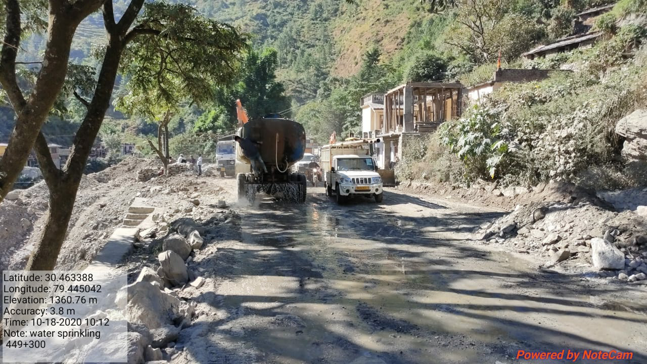
WATER POINTS
 1). The requirement of water, though not forming part of quarrying is an essential component for road construction and hence mentioned in this Technical Instruction. 
2). The water points along the alignment of the road must also be mentioned in Road Register and indicated on the plan. 
This will help in the planning works in the future, whenever needed. While indicating water points, their nature like perennial, rainfed, snowed, etc. must also be indicated suitably. 3).Whenever required/possible, masonry/static storage tanks with discharge spouts for gravity feed into the water trucks should be constructed to obviate the need for pumping.

Thursday, October 1, 2020

Standard Penetration Test (SPT), WHAT IS PROCEDURE OF STANDARD PENETRATION TEST?

Standard Penetration Test (SPT) The SPT is carried out in a borehole, while SCPT is carried out without a borehole. These tests examined the resistance of soil strata to penetration. • This is the most completely used penetrometer test and employs a split spoon sampler. The SPT is carry-out by driving a standard split spoon sampler into the ground by blows from a drop hammer of mass 64 kg drop-down760 mm. The sampler is driven 150 mm into the soil at the bottom of the borehole and the number of blows (N) essential to drive it an additional 300 mm counted. The number of blows (N) is represented by the standard penetration number.

Soil Sampling Method, Types of Soil Samples

Soil Sampling Methods In general, soil samples are categorized as given below Disturbed Samples • Change in the stress condition. • Change in the water content and the void ratio. • Chemical changes. • Change in the soil structure. • In remoulding sample, the engineering properties get changed due to remoulding. Undisturbed Samples • For undisturbed samples, the stress changes cannot be avoided. Undisturbed Samples • It maintains nearly workable the correct in-situ structure and water content of the soil. • For undisturbed samples, the stress changes cannot be kept away from. • An undisturbed sample is that in which the natural structure and asset remain to maintain.

Bonds in Brick Masonry 

The arrangement of bricks in order to tie them together in a mass of brick work is called bonding. 

Different types of bonds in brick masonry are given below 

• Stretcher Bond In this type of bond, all the bricks are laid as stretchers on the faces of walls. It is suitable for half brick walls only.

 • Header Bond In this type of bond, all the bricks are laid as headers on the faces of walls. It is suitable for one brick wall only. 

English Bond

The vertical joints in the header courses come over each other and vertical joints in the stretcher courses are also in the same line. In this bond, the heading course should never start with a queen closer. 

• Flemish Bond

 This types of Bond, each course consists of alternate headers and stretchers. 

The alternate headers of each course are centrally supported over the stretched below it.

Closer A portion of a brick cut longitudinally with one long face uncut. 


Thursday, September 24, 2020

What is defined a Stone Masonry?, What is Types of Rubble Masonry?

Stone Masonry 
When rock is quarried out and given rough shape at quarries it is called stone masonry. 
The stone masonry may be classified as follows 
Rubble Masonry 
In this masonry the stones of disorder sizes are used. 
The following of rubble masonry are given below.
Coursed Rubble Masonry 
This is the rough and cheap way of stone walling.
 In this type of rubble masonry, the stones used are various sizes such as from 50 mm to 200 mm.
 This type of stone masonry is commonly used in the construction of public buildings residential buildings, etc.
 • Uncoursed Rubble Masonry
this type of rubble masonry, the stones are not formalize.
The courses are not maintained regularly. 
 • Random Rubble Masonry
 In this type of rubble masonry, the stones of irregular sizes and shapes are used. The stones are arranged, therefore as to have a good guise. 

Random Rubble Masonry  is used in residential building, compound wall, godown, etc.
 • Dry Rubble Masonry 
This type of rubble masonry is similar in construction to coursed rubble masonry except that no mortar is used in the joints. It is  used for compound walls, retaining walls and pitching on bridge approaches slab, etc. 

Ashlar masonry 
The square or rectangular blocks of stone are used in this type of masonry. 
The height of stone varies from 250 mm to 300 mm.
 The length of stones should not exceed three times the height and the depth into the wall should be at least equal to half the height.

Galvanized iron

Galvanized iron
 Galvanized sheet is a widely used building project material.
 this iron is coated with a zinc oxide finish, making it superior to plain steel.
  Galvanized iron is most often used in pipes, roofs, support, beams, wall braces, and residential framing.

Saturday, September 19, 2020

Bitumen & Types of Bitumen

Bitumen
  Bitumen is the product obtained by fractional distillation of crude petroleum as an end product. 
• Bitumen becomes soft at moderate temperatures. It can be modified by heating until it becomes a liquid and then passing air under pressure by which all the volatile compounds in it can be driven out.
 The product is called "blown bitumen" (R grade).
Bitumen is available in the following forms:-
 (1)• Straight Run Bitumen
 It refers to bitumen distilled to a definite viscosity of penetration which does not require further treatment like heating.
 (2)• Penetration Grade
 It is the basic form of bitumen and has to be heated before application.
 (3)• Cutback Bitumen 
It is the bitumen combined with other petroleum distillates.
 This may be regarded as means of. applying penetration-grade bitumen at lower temperatures.
(5) • Bitumen Emulsion 
It is a product in liquid form formed in aqueous medium and stabilizing agents.
 This is also another means to obtain bitumen into a liquid form so that it can easily be applied at ambient temperature. 
(6)• Plastic Bitumen 
It consists of bitumen thinner and suitable filler made into a plastic form. As it is plastic, it can be used for filling cracks is masonry, stopping leakages, etc. 

(7)• Residual Bitumen 
It is a solid substance at normal temperature and is obtained as a residue during distillation of high-resin petroleum.


दिल्ली सहारनपुर देहरादून एक्सप्रेसवे

9 निर्माण फर्मों ने 18 मई 2022 को  210 किलोमीटर दिल्ली-सहारनपुर-देहरादून एक्सप्रेसवे के चरण 3 के 18.47 किलोमीटर पैकेज 2 के निर्माण क...