Monday, September 2, 2024

Types of drawings in any construction project:

Types of drawings in any construction project:

1. IFC Drawing:

Detailed drawings considered final, issued, and approved by the design team for construction, reflect precise dimensions, layout, and specifications. It can used by GCs to execute construction according to the contract, and also serve as a legal record of the design.

2. Construction Drawings:

These drawings provide an overview of the entire project, its floor plans, elevations, sections, and site plan. These documents are used in bidding and early construction stages.

3. Shop Drawing:

Detailed drawings produced by contractors or sub-contractors, illustrating specific components, systems, or installations according to design.

4. As-Built Drawings:

Drawings created during or after construction that show/reflect the actual conditions of the project, including any changes or modifications made during construction.

Summary:

i. IFC drawings represent the entire project design.

ii. Shop drawings focus on specific components.

iii. Construction drawings provide an overview.

iv. As-built drawings capture the final built state.

Thursday, June 8, 2023

दिल्ली सहारनपुर देहरादून एक्सप्रेसवे

9 निर्माण फर्मों ने 18 मई 2022 को  210 किलोमीटर दिल्ली-सहारनपुर-देहरादून एक्सप्रेसवे के चरण 3 के 18.47 किलोमीटर पैकेज 2 के निर्माण के लिए बोलियां जमा कीं।
 यह 6 लेन ज्यादातर ग्रीनफील्ड एक्सप्रेसवे 4 चरणों में विकसित किया जा रहा है। इसके 40 किलोमीटर के चरण 3 में NH-307 को उत्तर प्रदेश के सहारनपुर बाईपास और उत्तराखंड के गणेशपुर के बीच 6 लेन के एक्सेस-नियंत्रित राजमार्ग में अपग्रेड किया जाएगा।

 इस पैकेज में 2 निरंतर खंड शामिल हैं।
 और इसकी विस्तृत परियोजना रिपोर्ट (डीपीआर) ट्रांसिस कंसल्टिंग प्राइवेट लिमिटेड द्वारा तैयार की गई थी। 
 भारतीय राष्ट्रीय राजमार्ग प्राधिकरण (NHAI) ने जनवरी 2022 में अपने निर्माण अनुबंध के लिए रुपये के साथ निविदाएं आमंत्रित कीं। 495.85 करोड़ अनुमान और 10 साल की रखरखाव अवधि। 

एनएचएआई का संक्षिप्त दायरा: बीएमपी चरण-1 (पैकेज-2) के तहत ईपीसी पर उत्तर प्रदेश और उत्तराखंड में सहारनपुर बाईपास से दिल्ली देहरादून ईसी के गणेशपुर खंड तक के हिस्सों में पूर्ण अभिगम नियंत्रण प्रावधानों के साथ छह लेन (पैकेज -2)। 

Flexible Pavement, Construction of Road or Highway

Construction of Road/ Highway
There are two types of Road Construction.
 1.) Flexible Roads/Pavement
 2.) Rigid Roads/Pavement
 In Flexible Road Construction
 Total length of thickness=570mm
 a) GSB Layers=300 mm
 b) Wet mix macadam (WMM) Layer=120 to 150 mm
 c)  Dense Bituminous Macadam (DBM) = 80 mm
 d) Bituminous Course (BC)/Wearing Course = 40 mm
 Total =300+150+80+40
           =570 mm

Flexible Pavement 
A pavement which consists of a mixture of asphaltic or bituminous material and aggregate placed on a good quality and compacted granular material is called flexible pavement. Example of flexible pavement water bound macadam roads . 
The essential points of flexible pavement 
(i) The flexible pavements have self revive properties.whatever deformation arise in flexible pavement due to massive wheel loads, it is regeneration to some extent after some time. 
(ii) The temperature variations due to changes in atmospheric conditions do not produce stresses in flexible pavement. 
(iii) The structural capacity of the flexible pavement is influenced by strength of the sub-grade. 
(iv) The cost of construction of flexible pavements is less than compared to rigid pavement. 

California bearing Ratio Method

Construction of Road/ Highway
There are two types of Road Construction.
 1.) Flexible Roads/Pavement
 2.) Rigid Roads/Pavement
 In Flexible Road Construction
 Total length of thickness=570mm
 a) GSB Layers=300 mm
 b) Wet mix macadam (WMM) Layer=120 to 150 mm
 c) Dense Bituminous Macadam (DBM) = 80 mm
 d) Bituminous Course (BC)/Wearing Course = 40 mm
 Total =300+150+80+40
           =570 mm
California bearing Ratio Method 
The California bearing ratio of a soil which ranges from 0 to 100 % , gives a value about the quality of a material contrast to that of a magnificent base material for which the C.B.R. is assumed to be 100 percent. 
There are many versions of C.B.R. method of flexible pavement design. 
 
This is a penetration test developed by the California Division of Highways to evaluate the stability of soil sub-grade and other flexible pavement. 
It contains a standard piston have a diameter of 50 mm which is used to penetrate the soil at the standard value of 1.25 mm/min. 
Test Procedure
(a) Laboratory CBR apparatus contain a mold of 150 mm diameter with a base plate and a collar, a loading framework and dial gauges to evaluate the penetration. 
(b)The specimen of soil is soaked in water for 4 days, and swelling and water absorption values is noted. 
(c) Load is applied on the samples by a standard plunger with diameter of 50 mm at the rate of 1.25 mm/minutes.
(d) A graph is plotted between the load or pressure and penetration. 
(e) Load values are noted corresponding to the 2.5 mm and 5.0 mm penetration.
 (f) Calculate the CBR value corresponding to 2.5 mm and 5.0 mm. 
CBR% = (Load carried by specimen at 2.5 or 5.0 mm penetration/ Load carried b standard aggregates at a corresponding penetration level ) x 100
 Standard Load Values 
Penetration (mm)  Load (Kg) Pressure (Kg/Cm^2) 
2.5   1370 70 
5.0 2055 105
 (g) Average CBR value of three test specimens is reported as the CBR value of the sample. Table.1 Typical CBR values of soils and their rating 
Soil Range of CBR values   Rating
Clay.    2-5     very poor Subgradade
Silt           5-8 Poor Subgrade
 Sand    8-20 Fair to good Subgrade
GRAVEL 20-30  Excellent Sub grade  

What do you understand by Water cement ratio? How the quantity of water affects the strength of a Concrete mix?

 WATER CEMENT RATIO
The ratio of the volume of water to volume of cement used in a concrete mix is called water cement ratio. 
By Water. Cement ratio Law
According to water cement ratio Law, "For any given condition of test, the strength of well compacted Concrete with good workability is dependent only on the water cement ratio."
The workability of Concrete is dependent to other factors like grading of Concrete, proportion of aggregates, proportion of cement, and the efficiency of mixture etc. Also depends upon the quantity of water used in the mixture.
According to Abram law the strength of mixture increases not merely by increasing the quantity of cement in the mix but it is an account it of reducing the water cement ratio the strength of concrete in accordance with the the law is given by modified formula.
P28= 984/4^x
Where P28 = Cylinder Crushing Strength of Concrete in Kg/cm^2
X= Water Cement ratio by volume
The observation results, it is observed that for a given proportion of ingredients in a design concrete mix, there is almost a certain around of water (optimum) which gives maximum strength.
 A small changes in the quantity of water reason much higher variation in the strength of concrete.
 In case the water used is less, the resultant concrete will be comparatively dry, difficult to place in position and may pose problems in compaction.
 Moreover, with less water complete setting of cement cannot be ensured and hence the strength of concrete get reduced appreciably.
 On the other hand, in case the water is more it would Tesult in formation cr excessive voids and honey-combing in the set concrete, thereby reducing its density, strength and durability.
 so that, water cement ratio determine as a yard stick for achieving concrete of define strength.
 The lower the water cement ratio, the larger is the strength of the Design mix of Concrete. 
A rich mix of concrete gives higher strength than a lean mix, not because of more cenent but it is on account of the fact that concrete can be used with a lower water cement ratio.

SHOTCRETING OF Slope Protection Work

METHODOLOGY FOR SLOPE PROTECTION WORKS 

A. METHODOLGY FOR SHOTCRETING
1. A better base or foundation is necessary for conventional and successful application of shotcrete. 
Where the shotcrete is to be placed against earth surfaces as linings, such surfaces shall first be thoroughly compacted and trimmed to line and grade. Shotcrete shall not be placed on any surface which is frozen, spongy, or where there is frequent water. 
The surface shall be kept damp for several hours before applying shotcrete. 
2. Adequate and safe scaffolding shall be provided so that the operator can hold the nozzle at the optimum angle and distance from the surface for all parts of the work. 
The scaffolding shall be also given easy approach to the shotcrete surface for to assist in flattening and finishing, if such is specified. Scaffolding shall be constructed to permit undisturbed applications of the shotcrete wherever possible.
3. Sufficient clearance shall be provided around the wire mesh to permit complete encasement with sound concrete. 
The clearance needed depends on the maximum size of aggregate in the mix and the size of wire mesh. 
The minimum clearance between the wire mesh and the form or other backup material may vary between 12 mm to 20mm,
 4. Each layer of shotcrete is built up by making several passes or loops of the nozzle over the working area. 
This may be done by moving the nozzle easily in a series of loops from side to side and uneven. 
The shotcrete shall emerge from the nozzle in a steady, undisturbed flow. If the flow becomes irregular due to any cause, the operator shall direct it away from the work until it again becomes constant. 
The distance of the nozzle from work (usually between 0.5 and 1.5 m) shall be such as to give the best results for the working conditions. 
The nozzle shall be held perpendicular to the surface of application. 
5. The mix shall be little wetter than normal, but not so wet as to cause sloughing behind the wire mesh. 
This procedure forces the plastic shotcrete behind the mesh while preventing build-up on the front face of the bar.
for wet spraying is mixed, the slump should be measured, and the slump should be 8 to 12 cm. 
6. Rebound is the process in which aggregate and cement paste which more times off the surface during the application of shotcrete due to collision with the hard surface, reinforcement, or with the aggregate particles oursleves . 
The amount of rebound shall not be more than 20% and rebound material shall not reused. 
7. Where a layer of shotcrete is to be covered by a succeeding layer, it shall first be agreed to take its initial set. Then all laitance, loose material and recover, shall be removed by brooming. Any laitance which has achieve final set shall be withdraw by sand-blasting and the surface cleaned with an air water jet. Moreover, the surface shall be thoroughly sounded with a hammer for drummy areas resulting from recover surface or lack of bond.
Dummy areas, sags, or other defects shall be carefully cut out and replaced with the succeeding layer. Surfaces to be shot shall be damp. 
8. At the last of every day work, or on ending work for any other reason, the shotcrete shall be do nothing off to a thin edge and then the work shall be restart on next day after cleaning the surface. . 
9. The permissible tolerance on the thickness of the work executed by shotcrete shall be 8 mm.
 10. For lengths of hose up to 30 m, air pressure at the gun shall be 0.3 N/mm2 or more. Where the length exceeds 30 m, the pressure shall be enlarged by 0.035 N/mms for each moreover 15 m of hose required, and by 0.035 N/mm* for each 7.5 m that the nozzle is raised above the gun. 
11. Batching by mass is- to be preferred and is strongly recommended. Aggregates may be batched by volume if periodic checks, are made to ensure that the masses are maintained within a required tolerance. Water may be batched either by mass or by volume. 12. The wet mix of pneumatic feed type of  carriage accessories is competent  of applying high quality, low-slump mortar or concrete with the constancy needed for general construction and repairing work. 
From a pressurized vessel in the equipment, the premixed materials and compressed air are discharged into the delivery hose.
 The material and air pass through the hose to the  art of shooting gun nozzle which is fitted with an air ring for injecting  supplementary compressed air. 
13. The bulk density of wet sprayed shotcrete can be 2200-2300 kg/m 3. 
The weight ratio of cement to sandstone is ideally 1. 0: 3. 5 to 1. 0: 4. 0, the water-cement ratio is ideally 0.42 to 0.50, and the sand ratio is ideally 50% to 60%. 
After the mixture.

14. The coarse aggregate should be made of hard and durable gravel or pebbles.
 The particle size should not be more than 10mm, the aggregate grade should be continuous grading, the fine aggregate should be hard and durable medium sand or coarse sand, the fineness modulus should be greater than 2. 5, the water content should be controlled at 5% - 7 %. 
15.The suitable accelerator should be selected according to the types of cement , w/c ratio, etc., and the initial setting time should not exceed 5 minutes, and the final setting time should not exceed 10 minutes.

 B. Methodology for Drilling and Grouting: Following Methodology shall be adopted for drilling and grouting Flattening/Removal of overburden slope, Cutting of unstable rock blocks and preparation of smooth surface. Scaling of loose materials/blocks, providing drain pipes and drain holes Use of Self Drilling Anchors of 32mm Dia of Strength 200 KN and it should be confirmed by carrying out pull out test on 1% or 10 Nos of bolts (whichever is lesser).
 Grouting with cement mortar 1:2,1:3 and 1:4 in sequences till complete refusal. In cement grout Cebex 100 admixture of 250 g can be used for every bag of cement.
 Fine aggregate complying with the requirements of grading zone-1 of table 4 of IS 383:1970. 
For grouting operation compressor shall be used and pressure shall be monitored, at start pressure shall be not less 0.25 MPa and it shall be increased up to 2.5 MPa in sequential manner. 
Pressure chart, duration of grouting and intake of grout shall be maintained. Constructing shotcrete walls with Drainage Holes Constructing rock trap ditches at the toe of the slopes Providing rock catch fences/walls along the slope to make the surrounding locations safe for public usage. Providing hanging chains or webs to slow down toppling of block. 
Allowing free-hanging mesh net to direct loose rock pieces to drop down only near the slope toe. 
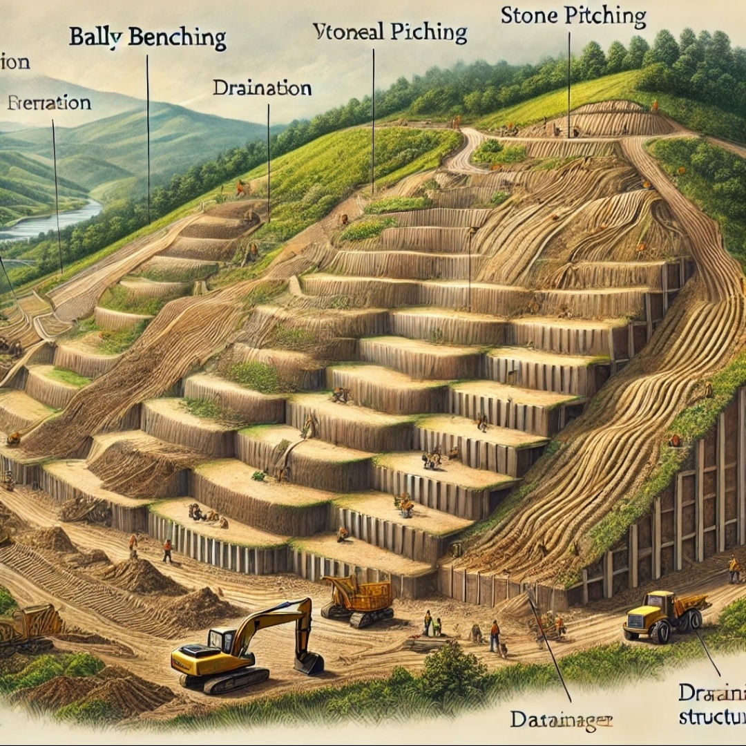
Constructing berms/benches as a rockfall collector. 
Providing mesh secured by bolts and grouted to protect friable formation

Casting yard में Kerbstone की Precast कैसे किया जाता है? KC Drain Site पर कैसे बनाया जाता है?

Casting yard में Kerbstone को Precast किया जाता है।
>Kerbstone का M-25 Grade में तैयार किया जाता है।
>Kerbstone का mould तैयार किया जाता है।
> Size of Kerbstone (आकार)
 लम्बाई- 18 इंच
चौड़ाई-14 इंच
मोटाई/गहराई -5 इंच
होता है। 
या

450 mm x 350 mm x 125 mm ( In Engineering)
> सीमेंट मोर्टार को तैयार करके Kerbstone mould में डालकर उसको Kerbstone block making machine पर  120 सेकेंड vibarting  करवाया जाता है। जिससे सीमेंट मोर्टार अच्छी तरह से संहनन हो जाए।
> इसके बाद उसको सुखने के लिए धूप में एक एक करके फैला दिया जाता है। जिससे अच्छी तरह से सूख जाए।
> Kerbstone को सुखाने के बाद समय पर तराई कार्य करते रहना चाहिए। जिससे यह अपनी अभिलाक्षणिक सम्पीडन सामर्थ्य प्राप्त कर सकें।
> Precast Kerbstone को KC Drain बनाने में उपयोग किया जाता है।
> Precast Kerbstone को casting yard से लेकर जाकर जहां पर (Site) पर रख लेते हैं।
> KC Drain के लिए सबसे पहले जहां पर Precast Kerbstone placing करना होता है, drawing के अनुसार अच्छी प्रकार से Surface Dressing करते हैं। और सतह को गीला करके 125 mm मोटाई की PCC work (M-15 Grade) किया जाता है। उसके बाद Precast Kerbstone placing करते हैं।
>Precast Kerbstone placing करते समय ढाल का ध्यान रखते हैं।
> Precast Kerbstone placing करते समय सही alignment (आरेखन) के लिए डोरी लगाया जाता है।
> Precast Kerbstone placing करने के बाद उनके बीच बचे रिक्त स्थानों में Groove filling सीमेंट मोर्टार से कर देते हैं।

> Kerbstone और सड़क स्तर के बीच वाली सतह पर 125 mm  मोटाई PCC कार्य (M-15 Grade) किया जाता है। जिससे अच्छी तरह से जल निकासी के लिए सतह प्राप्त हो सकें।

Types of drawings in any construction project:

Types of drawings in any construction project: 1. IFC Drawing: Detailed drawings considered final, issued, and approved by the design team f...